28 Rockwell Automation Publication 1766-UM001O-EN-P - September 2021
Chapter 2 Install Your Controller
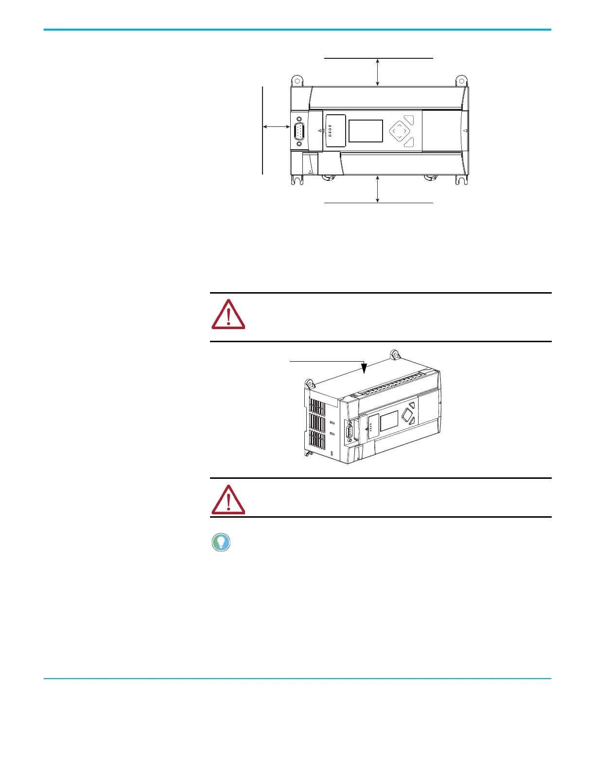
Figure 6 - Controller Spacing
Mount the Controller MicroLogix 1400 controllers are suitable for use in an industrial environment
when installed in accordance with these instructions. Specifically, this
equipment is intended for use in clean, dry environments (Pollution degree
2
(a)
) and to circuits not exceeding Over Voltage Category II
(b)
(IEC 60664-1).
(c)
DIN Rail Mounting
The maximum extension of the latch is 14 mm (0.55 in.) in the open position. A
flat-blade screwdriver is required for removal of the controller. The controller
can be mounted to EN50022-35x7.5 or EN50022-35x15 DIN rails. DIN rail
mounting dimensions are shown below.
(a) Pollution Degree 2 is an environment where, normally, only non-conductive pollution occurs except that occasionally a temporary
conductivity caused by condensation shall be expected.
(b) Over Voltage Category II is the load level section of the electrical distribution system. At this level transient voltages are controlled and do
not exceed the impulse voltage capability of the product’s insulation.
(c) Pollution Degree 2 and Over Voltage Category II are International Electrotechnical Commission (IEC) designations.
ATTENTION: Do not remove the protective debris shield until after the controller
and all other equipment in the panel near the controller are mounted and wiring is
complete. Once wiring is complete, remove protective debris shield. Failure to
remove shield before operating can cause overheating.
ATTENTION: Electrostatic discharge can damage semiconductor devices inside
the controller. Do not touch the connector pins or other sensitive areas.
For environments with greater vibration and shock concerns, use the panel mounting
method described on page 21, rather than DIN rail mounting.
 Loading...


