216 Rockwell Automation Publication 1766-UM001O-EN-P - September 2021
Appendix F MicroLogix 1400 Distributed Network Protocol
Basically, the index number of DNP objects of each type is evaluated by the
firmware automatically per the number of elements. For example, if a Binary
Input object file was configured as an element, the highest index number of
the Binary Input object is 15. The index number can only be increased by 16. If a
Double-bit Binary Input object file was configured as an element, the highest
index number of the Double-bit Binary Input object is 7. The index number can
only be increased by 8.
As another example, if a 16-bit Analog Input object file was configured as an
element, the highest index number is 1. Except for Binary and Double-bit
Binary type objects, the index number can be increased by 1.
DNP3 Configuration Files
You can set configuration files for each object. These configuration files allow
you to configure parameters such as Class level and Object Flag bit
information for each element. Only a Binary Data file type can be used for
configuration file.
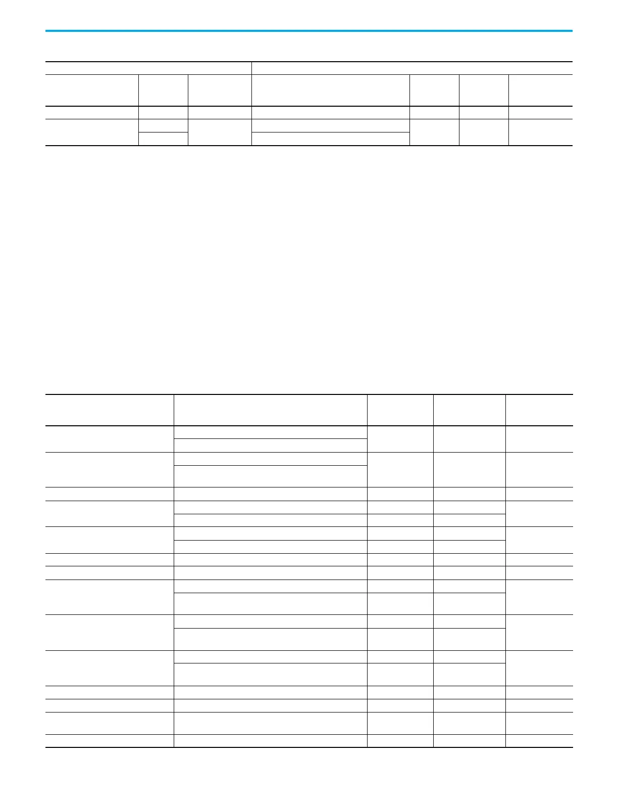
BCD Object 101 256 Small BCD Object File Only N file 7, 9…255 256
Data-Set Object(In Series B
and Series C)
85, 87, 88
10
Data-Set Prototypes Object File
Only N file 7, 9…255 10
86, 87, 88 Data-Set Descriptors Object File
Table 25 - Relationship between DNP3 Object Database and MicroLogix Data Files (Continued)
DNP Objects MicroLogix Data Files
Object Name
Related
Groups
Maximum
Configurable
Index
File name for Data File Type File Number
Maximum
Configurable
Elements
Table 26 - Relationship between MicroLogix Data Files and Configuration Files
MicroLogix Data Files Configuration Files File Type File Number
Maximum
Configurable
Elements
Binary Input File
Binary Input Config File
Only B file 3, 9…255 256
Binary Input Online Config File (In Series B and Series C)
Double Bit Binary Input File
Double-bit Binary Input Config File
Only B file 3, 9…255 256
Double-bit Binary Input Online Config File (In Series B and Series
C)
Binary Output File Binary Output Config File Only B file 3, 9…255 256
16-bit Counter File
16-bit Counter Config File Only B file 3, 9…255
256
16-bit Counter Threshold Config File (In Series B and Series C) Only N file 7, 9…255
32-bit Counter File
32-bit Counter Config File Only B file 3, 9…255
256
32-bit Counter Threshold Config File (In Series B and Series C) Only L file 9…255
Frozen 16-bit Counter File Frozen 16-bit Counter Config File Only B file 3, 9…255 256
Frozen 32-bit Counter File Frozen 32-bit Counter Config File Only B file 3, 9…255 256
16-bit Analog Input File
16-bit Analog Input Config File Only B file 3, 9…255
256
16-bit Analog Input Deadband Config File (In Series B and Series
C)
Only N file 7, 9…255
32-bit Analog Input File
32-bit Analog Input Config File Only B file 3, 9…255
256
32-bit Analog Input Deadband Config File (In Series B and Series
C)
Only L file 9…255
Short Floating Point Analog Input File
Short Floating Point Analog Input Config File Only B file 3, 9…255
256
Short Floating Point Analog Input Deadband Config File (In Series
B and Series C)
Only F file 8, 9…255
16-bit Analog Output File 16-bit Analog Output Config File (In Series B and Series C) Only B file 3, 9…255 256
32-bit Analog Output File 32-bit Analog Output Config File (In Series B and Series C) Only B file 3, 9…255 256
Short Floating Point Analog Output File
Short Floating Point Analog Output Config File (In Series B and
Series C)
Only B file 3, 9…255 256
Small BCD File Small BCD Class Config File Only B file 3, 9…255 256
 Loading...


