Rockwell Automation Publication 1766-UM001O-EN-P - September 2021 77
Chapter 5 LCD and Keypad
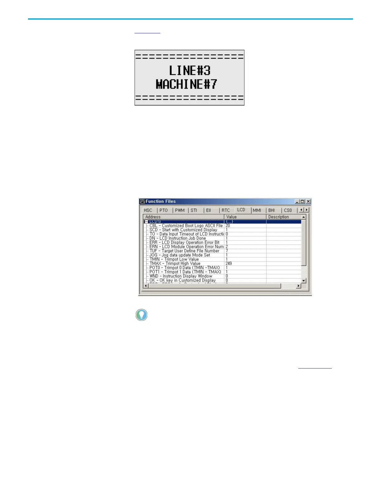
Figure 59 shows an example of a customized Startup screen.
Figure 59 - Customized Startup Screen Example
Your imported Bitmap file format should meet the following criteria:
• image resolution: 128 x 64 pixels (black/white image)
• image size: 1088 bytes
(consisting of image header = 62 bytes
+ raw image data size = 1024 bytes
+ padding data: 2 bytes)
To load a customized boot logo image to your controller, the CBL (Customized
Boot Logo ASCII File) element in the LCD Function File should be configured
properly. If the CBL element is set to 0 (default) or if the indexed ASCII file
does not exist, the embedded default logo displays.
For more information on how to create and use a customized Startup screen,
see the LCD Function File described in the MicroLogix 1400 Programmable
Controllers Instruction Set Reference Manual, publication 1766-RM001.
After the default Startup screen or your customized Startup screen displays for
3 seconds, either the default screen (the I/O Status screen) displays by default,
or a user-defined screen displays if your application uses a custom default
screen.
Main Menu and Default Screen
The Main menu consists of five menu items: I/O Status, Monitoring, Mode
Switch, User Display, and Advanced Set.
Once a valid bitmap file is imported successfully, you should see the data in ASCII data
files.
Make sure that the second element (file size) in the first ASCII data file is 0x0440 (1088
bytes) in hexadecimal value.
After a power cycle, you should see the customized boot logo on your LCD display.
 Loading...


