96 Rockwell Automation Publication 1766-UM001O-EN-P - September 2021
Chapter 5 LCD and Keypad
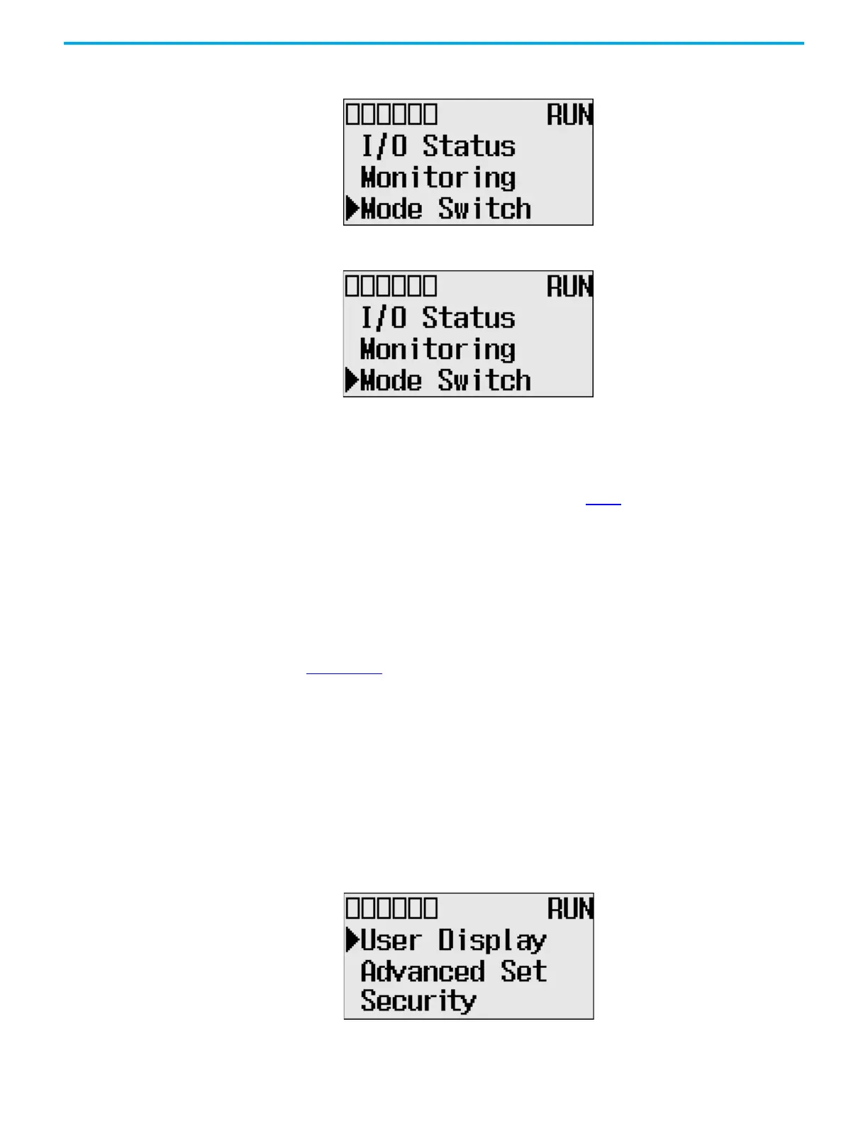
1. On the Main Menu screen, select Mode Switch by using the Up and Down
keys on the LCD keypad.
2. Press OK on the LCD keypad. The Mode Switch screen displays, as
shown.
The arrow indicates current Mode Switch position.
3. When the Up or Down key is pressed, the mode indicated by the arrow
blink if the mode is different from the current mode of controller. Press
OK to set the controller to the mode indicated by the arrow.
4. If you have finished changing mode switch position, press ESC to return
to the Main Menu screen, as shown in step 1
.
User-defined LCD Screen The MicroLogix 1400 controller allows you to use user-defined LCD screens
instead of the default built-in screens.
To use a user-defined screen, you need to create a group of appropriate
instructions using the LCD instruction in your application program. For more
information on how to create a user defined LCD screen, see MicroLogix 1400
Programmable Controllers Instruction Set Reference Manual, publication
1766-RM001
.
By using the User Display menu item, you can change from the default built-in
screens to a user-defined screen and back on the LCD.
User-defined LCD Screen
Follow these steps to display the user-defined screen implemented in your
application program.
1. On the Main Menu screen, select User Display by using the Up and Down
keys on the LCD keypad, as shown. If the menu items shown in the figure
below are not displayed on the Main Menu screen, scroll down the screen
by pressing the Down key.
Note: The Security menu is available in firmware revision 21.000 or later.
 Loading...


