220 Rockwell Automation Publication 1766-UM001O-EN-P - September 2021
Appendix F MicroLogix 1400 Distributed Network Protocol
DNP3 Binary Input Object
The supported object group and variations are listed in this section. The
controller responds with the default group and variation when the DNP3
Master requests to read the object with all variations.
Binary Input Static Objects:
• g1v0 – Binary Input – All Variations
• g1v1 – Binary Input – Packed format (default)
• g1v2 – Binary Input – With flags
Binary Input Event Objects:
• g2v0 – Binary Input Event – All Variations
• g2v1 – Binary Input Event – Without time
• g2v2 – Binary Input Event – With absolute time
• g2v3 – Binary Input Event – With relative time (default)
Related Object File Number:
• Binary Input Object File Number
Related Configuration File Number:
• Binary Input Config File Number
To generate a Binary Input Object from the DNP3 Subsystem in the controller,
you should configure Binary Input Object File Number in the DNP3 Slave
Application Layer Configuration file.
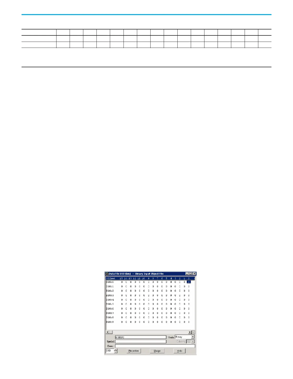
When the Binary Input Object File is configured, Index number starts from 0. 1
bit is used for 1 Index.
As an example, a Binary Input Object File is configured as shown below. This
file has 10 elements and 160 Binary Input points. Index 0 of the Binary Input
Object is B10:0/0, Index 1 is B10:0/1 and Index 159 is B10:9/15.
Element 5 rrrrrrrrrrrrrrC1C0
… C1 C0
r: reserved
C1/C0 : Class level, 0…3
For Small BCD, Element_0 for data index 0
P0: 0 for including Small BCD Data to Class 0 poll response
Small BCD Configuration File Data (Continued)
Bit Offset 15 14 13 12 11 10 9 8 7 6 5 4 3 2 1 0
 Loading...


