Rockwell Automation Publication 1766-UM001O-EN-P - September 2021 25
Chapter 2 Install Your Controller
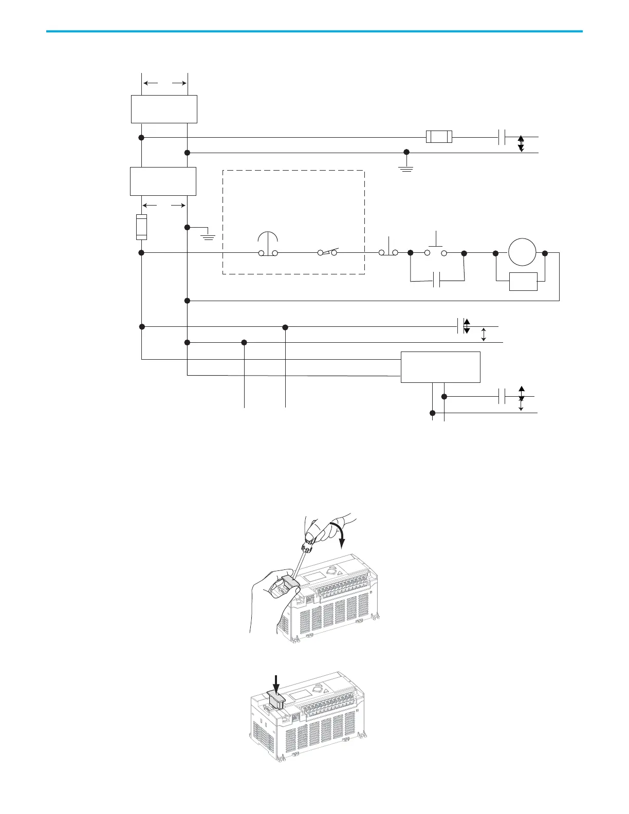
Figure 4 - Schematic (Using ANSI/CSA Symbols)
Install a Memory Module To install the memory module, do as follows:
1. Remove the memory module port cover.
2. Align the connector on the memory module with the connector pins on
the controller.
Emergency-Stop
Push Button
230V AC
Operation of either of these contacts will remove
power from the external I/O circuits, stopping
machine motion.
Fuse MCR
Fuse
MCR
MCR
MCR
Stop
Start
Line Terminals: Connect to terminals of Power Supply
(1766-L32AWA, 1766-L32AWAA, 1766-L32BWA, 1766-L32BWAA).
Line Terminals: Connect to 24V DC terminals of Power Supply
(1766-L32BXB, 1766-L32BXBA).
230V AC
Output Circuits
Disconnect
Isolation
Transformer
115V AC or
230V AC
I/O Circuits
L1
L2
Master Control Relay (MCR)
Catalog Number 700-PK400A1
Suppressor
Catalog Number 700-N24
(Lo)
(Hi)
DC Power Supply. Use NEC
Class 2 for UL Listing.
X1 X2
115V AC or
230V AC
_
+
MCR
24 V DC
I/O Circuits
Suppr.
Overtravel
Limit Switch
M
o
d
u
l
e
M
e
m
o
ry
 Loading...


