30 Rockwell Automation Publication 1766-UM001O-EN-P - September 2021
Chapter 2 Install Your Controller
2. Secure the template to the mounting surface. Make sure your controller
is spaced properly. See Controller and Expansion I/O Spacing on page 27.
3. Drill holes through the template.
4. Remove the mounting template.
5. Mount the controller.
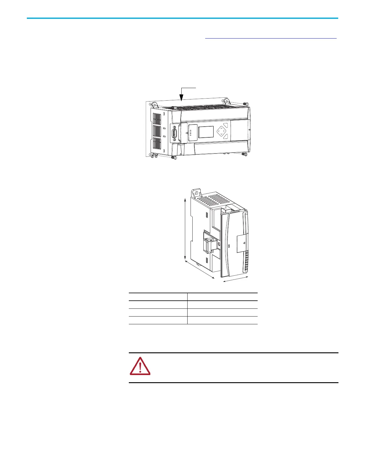
6. Leave the protective debris shield in place until you are finished wiring
the controller and any other devices.
1762 Expansion I/O
Dimensions
Expansion I/O Dimensions
Mount 1762 Expansion I/O
DIN Rail Mounting
The module can be mounted using the following DIN rails:
• 35 x 7.5 mm (EN 50 022 – 35 x 7.5), or
• 35 x 15 mm (EN 50 022 – 35 x 15).
ESC
OK
Dimension Measurement
A90 mm (3.5 in.)
B 40 mm (1.57 in.)
C 87 mm (3.43 in.)
ATTENTION: During panel or DIN rail mounting of all devices, be sure that all
debris such as metal chips and wire stands, is kept from falling into the module.
Debris that falls into the module could cause damage when the module is under
power.
 Loading...


