Rockwell Automation Publication 1766-UM001O-EN-P - September 2021 31
Chapter 2 Install Your Controller
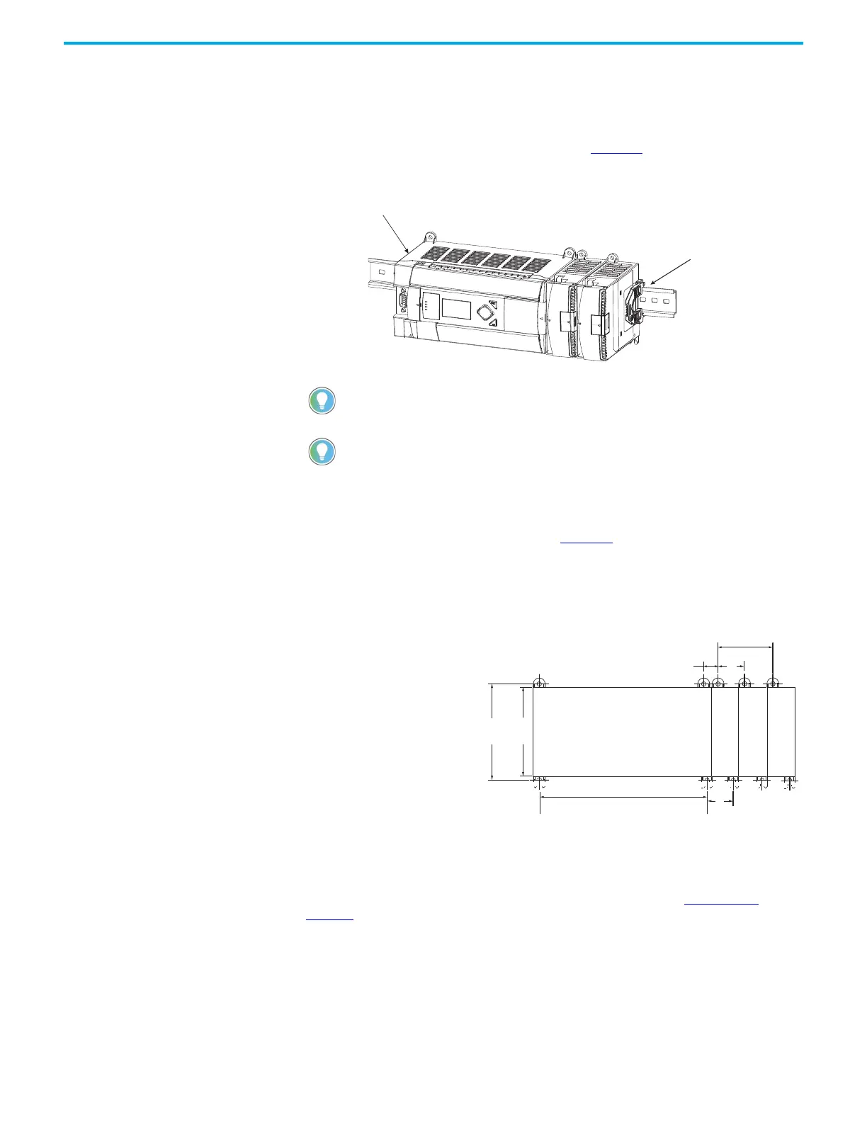
Before mounting the module on a DIN rail, close the DIN rail latch. Press the
DIN rail mounting area of the module against the DIN rail. The latch
momentarily opens and locks into place.
Use DIN rail end anchors (Allen-Bradley part number 1492-EA35 or 1492-
EAH35) for vibration or shock environments. Figure 7
shows the location of the
end anchors.
Figure 7 - End Anchor Position
Panel Mounting
Use the dimensional template shown in Figure 8 to mount the module. The
preferred mounting method is to use two M4 or #8 pan head screws per
module. Mounting screws are required on every module.
Figure 8 - Dimensional Template
Connect Expansion I/O The expansion I/O module is attached to the controller or another I/O module
by means of a flat ribbon cable after mounting, as shown in Figure 9 on
page 32.
1762 expansion I/O must be mounted horizontally as illustrated.
For environments with greater vibration and shock concerns, use the panel mounting
method described below, instead of DIN rail mounting.
90
(3.54)
100.06
(3.939)
40.4
(1.59)
A
40.4
(1.59)
14.2
(0.568)
MicroLogix
1400
1762 I/O
1762 I/O
1762 I/O
For more than 2 modules: (number of modules – 1) x 40 mm (1.59 in.)
NOTE: All dimensions are in mm (inches). Hole
spacing tolerance: ±0.4 mm (0.016 in.).
A = 165 mm (6.497 in.)
 Loading...


