Rockwell Automation Publication 1766-UM001O-EN-P - September 2021 37
Chapter 3 Wire Your Controller
This product is intended to be mounted to a well grounded mounting surface
such as a metal panel. See Industrial Automation Wiring and Grounding
Guidelines, publication 1770-4.1
, for additional information. Additional
grounding connections from the mounting tab or DIN rail, if used, are not
required unless the mounting surface cannot be grounded.
Wiring Diagrams The following illustrations show the wiring diagrams for the MicroLogix 1400
controllers. Controllers with DC inputs can be wired as either sinking or
sourcing inputs. Sinking and sourcing does not apply to AC inputs. See
Sinking and Sourcing Wiring Diagrams
on page 40.
The controller terminal block layouts are shown below. The shading on the
labels indicates how the terminals are grouped.
ATTENTION: All devices connected to the RS-232/485 communication port must
be referenced to controller ground, or be floating (not referenced to a potential
other than ground). Failure to follow this procedure may result in property
damage or personal injury.
• For 1766-L32BWA and 1766-L32BWAA controllers, the COM of the sensor supply is
also connected to chassis ground internally. The 24V DC sensor power source
should not be used to power output circuits. It should only be used to power input
devices.
• For 1766-L32BXB and 1766-L32BXBA controllers, the VDC NEUT or common
terminal of the power supply is also connected to chassis ground internally.
Use all four mounting positions for panel mounting installation.
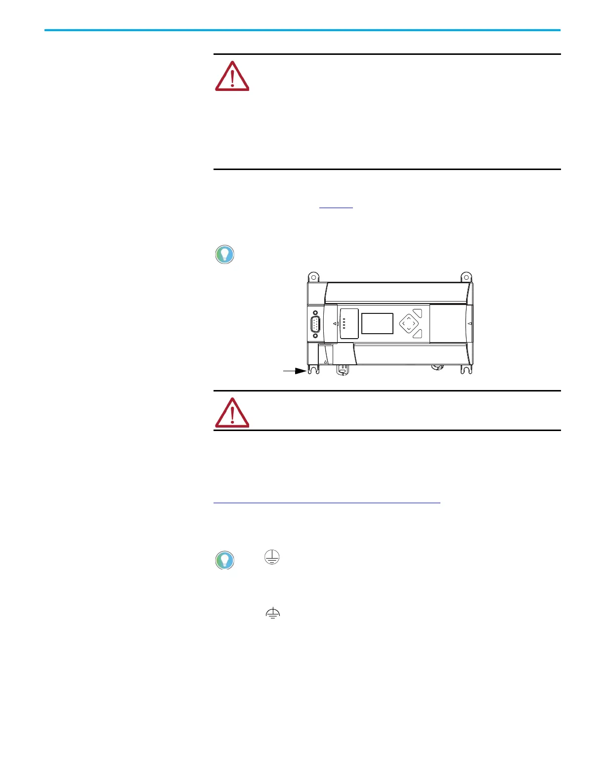
ATTENTION: Remove the protective debris strip before applying power to the
controller. Failure to remove the strip may cause the controller to overheat.
This symbol denotes a protective earth ground terminal which provides a low
impedance path between electrical circuits and earth for safety purposes and
provides noise immunity improvement. This connection must be made for safety
purposes on AC-powered controllers.
This symbol denotes a functional earth ground terminal which provides a low
impedance path between electrical circuits and earth for non-safety purposes, such
as noise immunity improvement.
 Loading...


