CONTROL UNIT
79
11
4
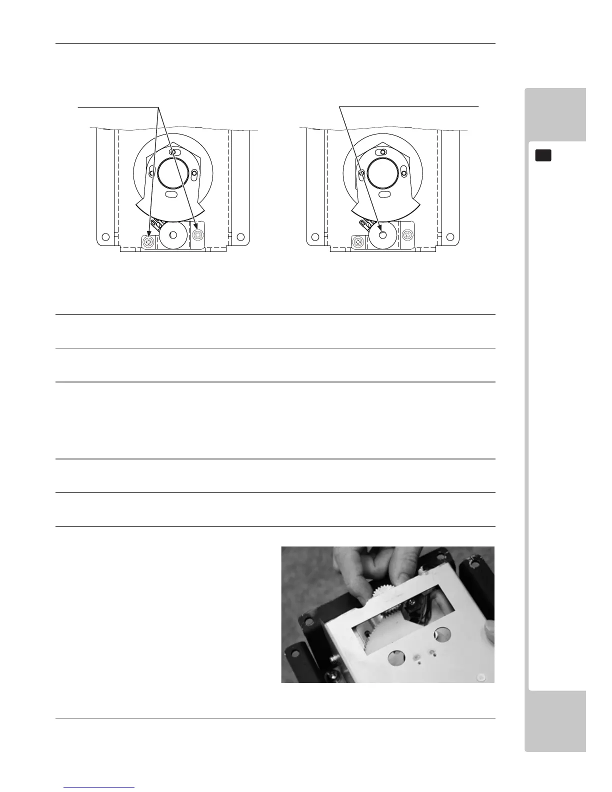
With the Control Unit’s left and right axis perpendicular to the screen, engage the D cut face of the volume
axis so that is matches the diagram below.
5
Tighten the two previously loosened screws.
6
Move the Control Unit left and right and check that the gears move smoothly.
7
Reattach the Control Unit, then turn on the power and adjust the volume value on the calibration screen.
FIG. 11-2b X Axis (Left and Right) Volume
You can also adjust the gear engagement in the following way.
1
Loosen the two screws xing the volume bracket lower and separate the gear engagement.
2
Looking at the bottom of the Control Unit from the top, turn it as far anti-clockwise as possible and hold it
there.
3
Turn the volume axis as far as it will go clockwise and then reengage the gears.
4
From this engagement, engage the gears on the volume axis at a half turn anti-clockwise and tighten the pre-
viously loosened screws.
FIG. 11-2c
Loosen the two screws.
GUN 1P GUN 2P
Volume axis D cut face with left and right
axis perpendicular to the screen

 Loading...