Programming via Rockwell controller
9.4 General structure of the add-on instructions
SIMATIC RF650R/RF680R/RF685R
160 Configuration Manual, 03/2018, C79000-G8976-C386-06
General structure of the add-on instructions
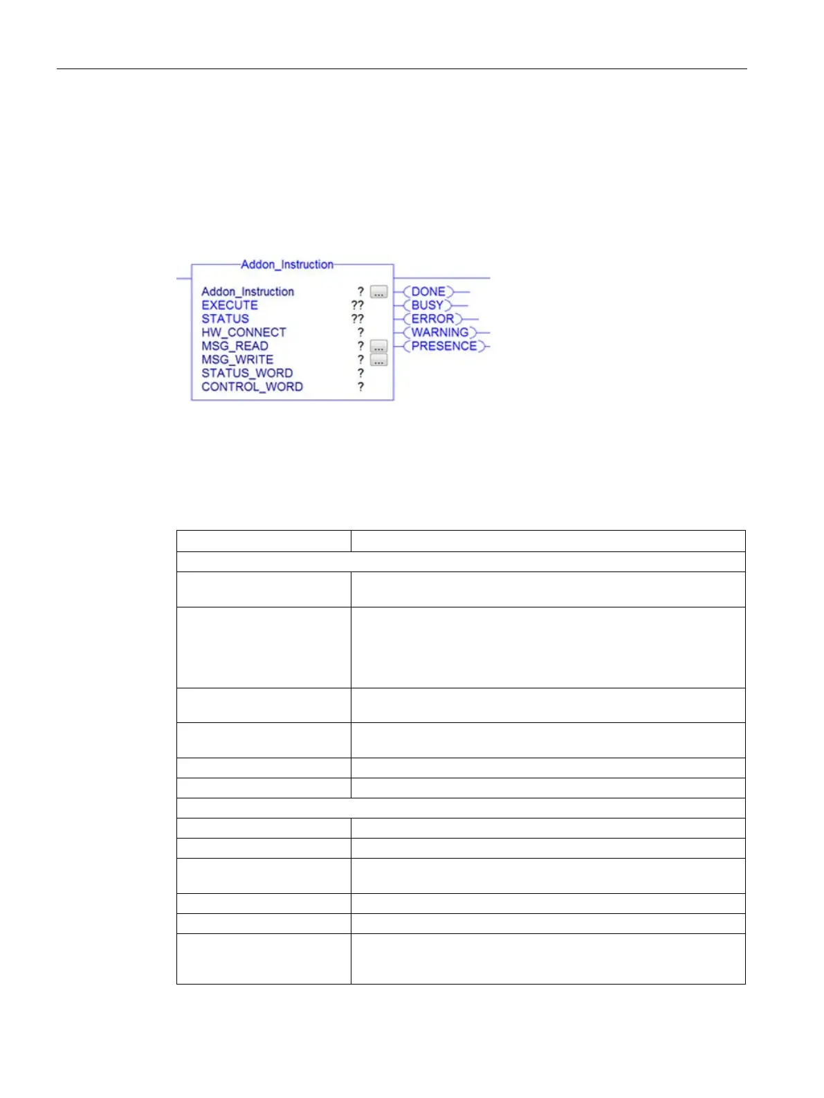
Structure of the blocks based on a sample block
The following graphic shows an example of a block with input and output parameters as they
exist in the same way in all blocks.
Figure 9-1 Example of a block
Description of the parameters
Table 9- 2 Description of the input and output parameters
EXECUTE There must be a positive edge at this input before the block will exe-
HW_CONNECT Global parameter of the type "IID_HW_CONNECT" to address the
channel/reader and to synchronize the blocks. This parameter is
located in the variables of the type "IID_DATA_RF68xR".
"HW_CONNECT" must always be transferred to the blocks to ad-
dress the relevant channel/reader.
MSG_READ Message variable for communication between the controller and
MSG_WRITE Message variable for communication between the controller and
reader
Cyclic status word which is sent from the reader to the contoller.
Cyclic control word which is sent from the controller to the reader.
The job was executed. If the result is positive, this parameter is set.
The job is being executed.
ERROR (BOOL) The job was ended with an error. The error code is indicated in Sta-
The job was ended with a warning.
Display of the error message if the "ERROR" bit was set.
PRESENCE (BOOL) This bit indicates the presence of a transponder. The displayed value
is updated each time the block is called. This parameter does not
occur in the blocks specifically for code reader systems.