Service and maintenance
12.1 Diagnostics
SIMATIC RF650R/RF680R/RF685R
282 Configuration Manual, 03/2018, C79000-G8976-C386-06
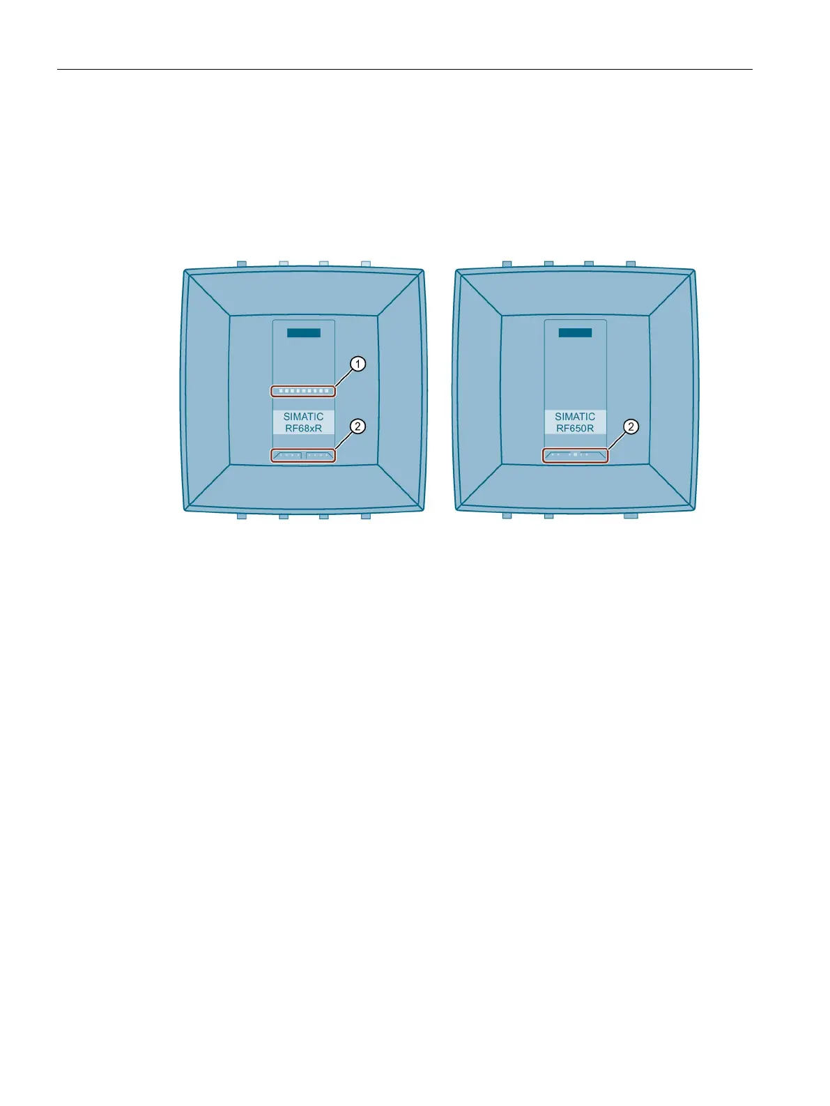
Diagnostics via the LED displays
Note that the RF650R reader does not provide an LED status display. With the help of the
LED displays, you can recognize the reader status and the error messages of the
RF680R/RF685R readers.
The LED status display is in the middle on the front of the reader. The LED operating display
it is at the bottom on the front of the reader.
LED status display (ST1 - ST9) - RF680R/RF685R only
• RUN/STOP (R/S)
Shows whether the reader is ready for operation.
• ERROR (ER)
Indicates whether an error has occurred.
• MAINTENANCE (MAINT)
- RF680R/RF685R only
Shows whether the reader needs maintenance.
• POWER (PWR)
Shows whether the reader is supplied with power.
• PRESENCE (PRE)
- RF650R only
Among other things, indicates whether or not there are multi-
ple transponders in the antenna field. With the
RF680R/RF685R readers, this is displayed with the status
• LINK 1 (LK1)
Indicates that there is a connection via Ethernet interface "1".
• RECEIVE/TRANSMIT 1
(R/T1)
Indicates that data is being sent and/or received via Ethernet
interface "1".
• LINK 2 (LK2)
- RF680R/RF685R only
Indicates that there is a connection via Ethernet interface "2".
• RECEIVE/TRANSMIT 2
(R/T2)
- RF680R/RF685R only
Indicates that data is being sent and/or received via Ethernet
interface "2".
Figure 12-1 LED displays of the reader
 Loading...