5-27
4. D Range Adjustment (PK-58 board)
Set the D range of the LCD driver to the specified value. If deviated,
the LCD screen will become blackish or saturated (whitish).
Mode Still (Auto ( ))
Subject Arbitrary
Measurement Point Pin 9 of CN302 (VG)
External trigger: Pin 8 of CN302
(COM)
Measuring Instrument Oscilloscope
Adjustment Page D
Adjustment Address D5
Specified Value A = 3.62 ± 0.05V
Adjusting method:
Order Page
Address
Data Procedure
1 0 01 01 Set the data.
2 4 F1 03 Set the data.
3 D D5 Change the data and set the
voltage (A) between the reversed
waveform pedestal and non-
reversed waveform pedestal to the
specified value.
4 D D5 Press PAUSE button.
5 4 F1 00 Set the data.
6 0 01 00 Set the data.
5. Bright Adjustment (PK-58 board)
Set the level of the VIDEO signal for driving the LCD to the specified
value. If deviated, the screen image will be blackish or saturated
(whitish).
Mode Still (Auto ( ))
Subject Arbitrary
Measurement Point Pin 9 of CN302 (VG)
External trigger: Pin 8 of CN302
(COM)
Measuring Instrument Oscilloscope
Adjustment Page D
Adjustment Address D0 CE, DE
Specified Value A = 1.81 ± 0.05V
Adjusting method:
Order Page
Address
Data Procedure
1 0 01 01 Set the data.
2 4 F1 03 Set the data.
3 4 10 01 Set the data.
4 D D0 Change the data and set the
voltage (A) between the pedestal
and GAMMA1 limiter level to the
specified value.
5 D D0 Press PAUSE button.
6 D D0 Read the data, and this data is
named DD0.
7 Convert DD0 to decimal notation,
and obtain DD0’. (Note)
8 Calculate DCE’ and DDE’ using
following equations (Decimal
calculation)
DCE’=DD0’–12
DDE’=DD0’+32
9 Convert DCE’ and DDE’ to
hexadecimal number, and obtain
DCE and DDE. (Note)
10 D CE DCE Set the data, and press PAUSE
button.
11 D DE DDE Set the data, and press PAUSE
button.
12 4 10 00 Set the data.
13 4 F1 00 Set the data.
14 0 01 00 Set the data.
Note: Refer to “Table 5-4-1. Hexadecimal-decimal Conversion Table”.
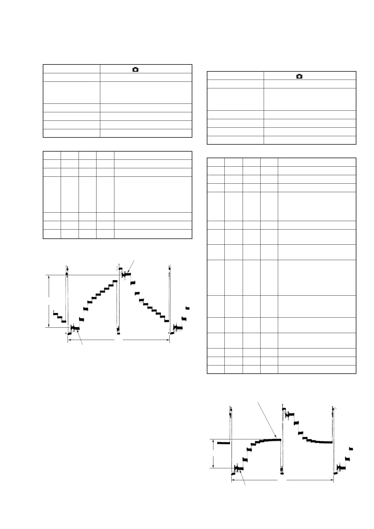
Fig. 5-1-17.
Fig. 5-1-18.
A
2H
Pedestal
Pedestal
A
2H
GAMMA 1 limiter level
Pedestal

 Loading...