5-5
H
A=B
C=D
AB B
CD
A
Enlargement
V
Electronic beam scanning frame
Effective picture frame
CRT picture
frame
B
A
Difference in level
Yellow
Cyan
Green
White
Magenta
Red
Blue
Yellow
Cyan
Green
White
Magenta
Red
Blue
Video terminal
output waveform
Fig. b (monitor TV picture)
Fig. a
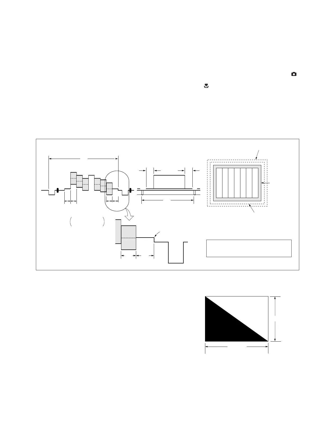
Color bar chart (Color reproduction adjustment frame )
Adjust the camera zoom and direction to
obtain the output waveform shown in Fig. a
and the TV monitor display shown in Fig. b.
White
Black
841m
1189mm
1-1-4. Precaution
1. Setting the Switch
Unless otherwise specified, set the switches as follows and perform
adjustments.
SETUP settings
DEMO MODE (SETUP2) ...............................................OFF
VIDEO OUT (SETUP2) ...............................................NTSC
MENU settings
1. WHITE BALANCE ..................................................... AUTO
2. ISO ............................................................................... AUTO
3. IMAGE SIZE ............................ 2048 × 1536 (MVC-CD300)
............................ 1600 × 1200 (MVC-CD200)
4. PICTURE EFFECT .........................................................OFF
Switch settings
1. Mode dial .............................................................. Auto ( )
2. ZOOM W ............................................................... WIDE end
3. MACRO (
) .................................................................. Off
4. FOCUS (PK-58 board) ................................... Manual (0.3m)
5. EV (PK-58 board) ............................................................0EV
6. AE LOCK (PK-58 board) ................................................. Off
2. Order of Adjustments
Basically carry out adjustments in the order given.
Fig. 5-1-6.
3. Subjects
1) Color bar chart (Color reproduction adjustment frame)
When performing adjustments using the color bar chart, adjust
the picture frame as shown in Fig. 5-1-6. (Standard picture
frame)
2) Clear chart (Color reproduction adjustment frame)
Remove the color bar chart from the pattern box and insert a
clear chart in its place. (Do not perform zoom operations during
this time.)
3) Flange back adjustment chart
Make the chart shown in Fig. 5-1-7 using A0 size (1189mm ×
841mm) black and white vellum paper.
Fig. 5-1-7.
Note: Use matte vellum paper bigger than A0, and make sure the edges of
the black and white paper joined together are not rough.

 Loading...