5-20
12.Color Reproduction Adjustment
Adjust the color Separation matrix coefficient so that proper color
reproduction is produced.
12-1. Color Reproduction Adjustment
Mode Still (Auto ( ))
Subject Color bar chart
(Color bar standard picture frame)
Adjustment Page F
Adjustment Address 41 to 48, 5C to 5F
Note1: This adjustment should be carried out upon completion of “Data
Setting during Camera System Adjustments”.
Note2:
After the power is turned on, this adjustment can be done only once.
Note3: Check that the data of page: 6, address: 02 is “00”. If not, turn off
the power and turn on again.
Note4: This adjustment must be performed in NTSC mode.
Switch setting:
ZOOM .................................................................... WIDE end
FOCUS............................................................ Manual (0.3m)
Adjusting method:
Order Page
Address
Data Procedure
1 0 01 01 Set the data.
2 B 75 Check that the data is “00”.
(Note1)
3 6 12 80 Set the data, and wait for 1 sec.
4 6 12 00 Set the data, and wait for 2 sec.
5 6 01 A9 Set the data, and press PAUSE
button.
6 6 02 Check that the data changes to
“01”. (Note5)
Note5: The adjustment data will be automatically input to page: F, address:
41 to 48, 5C to 5F.
Processing after Completing Adjustments:
Order Page
Address
Data Procedure
1 6 01 00 Set the data, and press PAUSE
button.
2 0 01 00 Set the data.
12-2. Color Reproduction Check
Mode Still (Auto ( ))
Subject Color bar chart
(Color bar standard picture frame)
Measurement Point Video output terminal
Measuring Instrument NTSC vectorscope
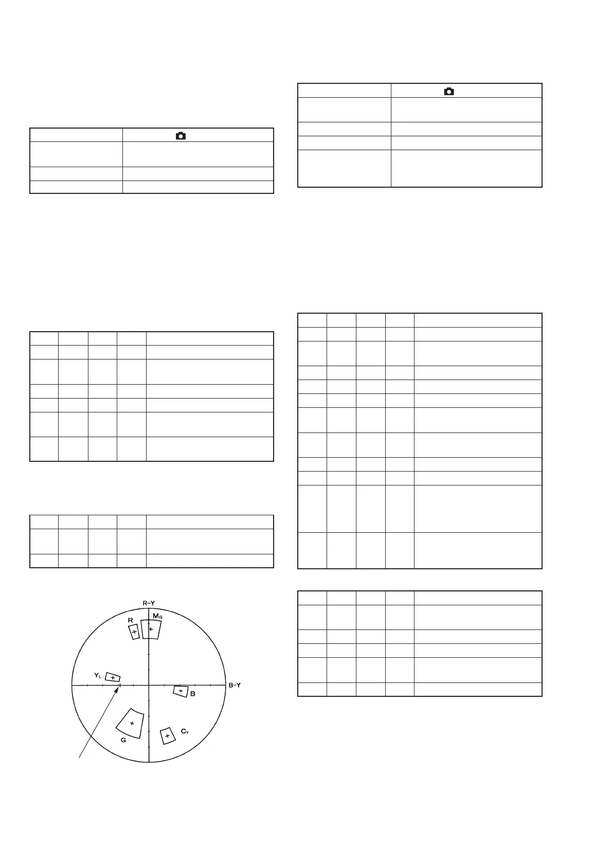
Specified Value Each center of all color luminance
points should settle within each color
reproduction frame.
Note1: This adjustment should be carried out upon completion of “Data
Setting during Camera System Adjustments”.
Note2: This adjustment must be performed in NTSC mode.
Note3: Check that the data of page: 6, address: 02 is “00”. If not, to page:
6, address: 01, set data: 00, and press the PAUSE button.
Switch setting:
ZOOM .................................................................... WIDE end
FOCUS............................................................ Manual (0.3m)
Checking method:
Order Page
Address
Data Procedure
1 0 01 01 Set the data.
2 B 75 Check that the data is “00”.
(Note1)
3 4 06 01 Set the data.
4 6 10 01 Set the data.
5 E 52 Write down the data.
6 E 52 09 Set the data, and press PAUSE
button.
7 6 01 0F Set the data, and press PAUSE
button.
8 6 12 80 Set the data, and wait for 1 sec.
9 6 12 00 Set the data, and wait for 2 sec.
10 Adjust the GAIN and PHASE of
the vectorscope so that the burst
luminance point is set at the
specified position.
11 Check that each center of all color
luminance points is set in each
color reproduction frame.
Processing after Completing Adjustments:
Order Page
Address
Data Procedure
1 6 01 00 Set the data, and press PAUSE
button.
2 6 10 00 Set the data.
3 4 06 00 Set the data.
4 E 52 Set the data that is written down
at step 5, and press PAUSE button.
5 0 01 00 Set the data.
Burst position
Fig. 5-1-13.
RadarWRadarWRadarWRadarWRadarW

 Loading...