5-12
1-4. CAMERA SYSTEM ADJUSTMENTS
Before perform the camera system adjustments, check that the
specified values of “VIDEO SYSTEM ADJUSTMENT” are
satisfied.
Note: If “CLOCK SET” display appeared in the screen after the power is
turned on, set the clock, or cancel the display.
Data Setting during Camera System Adjustments
Perform the following data setting before the camera system
adjustments.
1) Select page: 0, address: 01, and set data: 01.
2) Input the following data.
Note: Press the PAUSE button each time to set the data.
After completing the camera system adjustments, release the data
setting.
1) Select page: 0, address: 01, and set data: 01.
2) Input the following data.
Note: Press the PAUSE button each time to set the data.
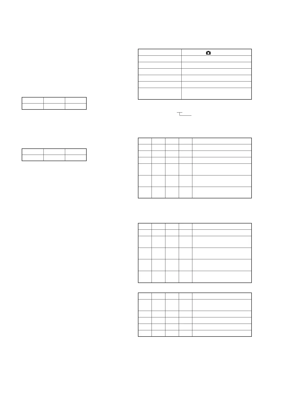
1. HALL Adjustment (MVC-CD200)
For detecting the position of the lens iris, adjust the hall AMP gain
and offset.
Mode Still (Auto ( ))
Subject Arbitrary
Measurement Point Display data of page 1 (Note1)
Measuring Instrument Adjustment remote commander
Adjustment Page F
Adjustment Address 2E, 2F, 34, 35
Specified Value 12 to 16 during IRIS OPEN
77 to 7B during IRIS CLOSE
Note1: Displayed data of page 1 of the adjustment remote commander.
1 : 00 : XX
Display data
Note2: If the data of page: 6, address: 02 is “01”, select page: 6, address:
01, set data: 00, and press the PAUSE button.
Adjusting method:
Order Page
Address
Data Procedure
1 0 01 01 Set the data.
2 6 94 14 Set the data.
3 6 95 79 Set the data.
4 6 01 6D Set the data, and press PAUSE
button.
5 6 02 Check that the data changes to
“01”. (Note3)
6 6 01 00 Set the data, and press PAUSE
button.
Note3: The adjustment data will be automatically input to page: F, address:
2E, 2F, 34, 35.
Checking method:
Order Page
Address
Data Procedure
1 0 03 03 Set the data.
2 6 01 01 Set the data, and press PAUSE
button.
31
Check that the display data (Note1)
satisfies the specified value 1.
4 6 01 03 Set the data, and press PAUSE
button.
51
Check that the display data (Note1)
satisfies the specified value.2.
Processing after Completing Adjustments:
Order Page
Address
Data Procedure
1 6 01 00 Set the data, and press PAUSE
button.
2 6 94 00 Set the data.
3 6 95 00 Set the data.
4 0 03 00 Set the data.
5 0 01 00 Set the data.
3) Select page: 0, address: 01, and set data: 00.
SET UP Setting during Camera System Adjustments
VIDEO OUT (SETUP2) ....................... NTSC (NTSC mode)
Page
B
Address
75
Data
00
Page
B
Address
75
Data
10
RadarWRadarWRadarW

 Loading...