MVC-CD200/CD300
4-64
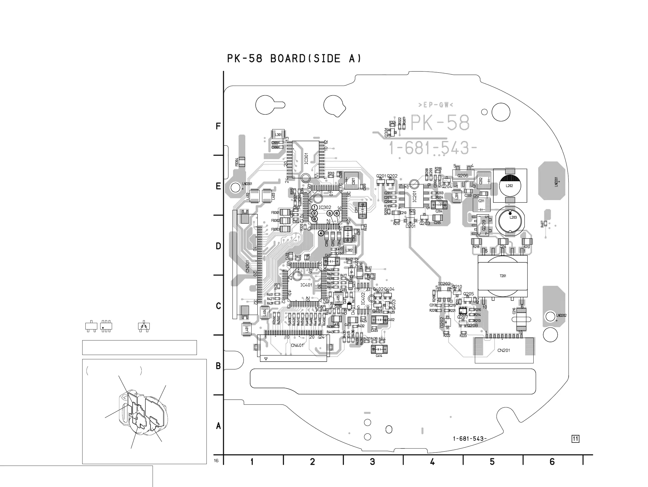
RGB DRIVE, TIMING GENERATOR, BACK LIGHT
PK-58
PK-58 (RGB DRIVE, TIMING GENERATOR, BACK LIGHT) PRINTED WIRING BOARD
— Ref. No. PK-58 Board; 4,000 Series —
JK-208
(USB INTERFACE)
PK-58
(RGB DRIVE, TIMING GENERATOR, BACK LIGHT)
CD-333 (CD200)
(LENS DRIVE, CAMERA PROCESS, CCD IMAGER)
FS-83
(CHARGER)
MD-083
CD-RF PROCESS, SERVO, CD, DSP,
CD-R/RW GA, MD SYSTEM CONTROL,
EFM/ENC CONTROL
For printed wiring board
• Refer to page 4-79 for parts location.
• PK-58 board consists of multiple layers. However, only
the sides (layers) A and B are shown.
• Chip parts
Transistor Diode
There are a few cases that the part printed on
this diagram isn’t mounted in this model.
C
BE
5
64
2
13
3
21

 Loading...