2-2
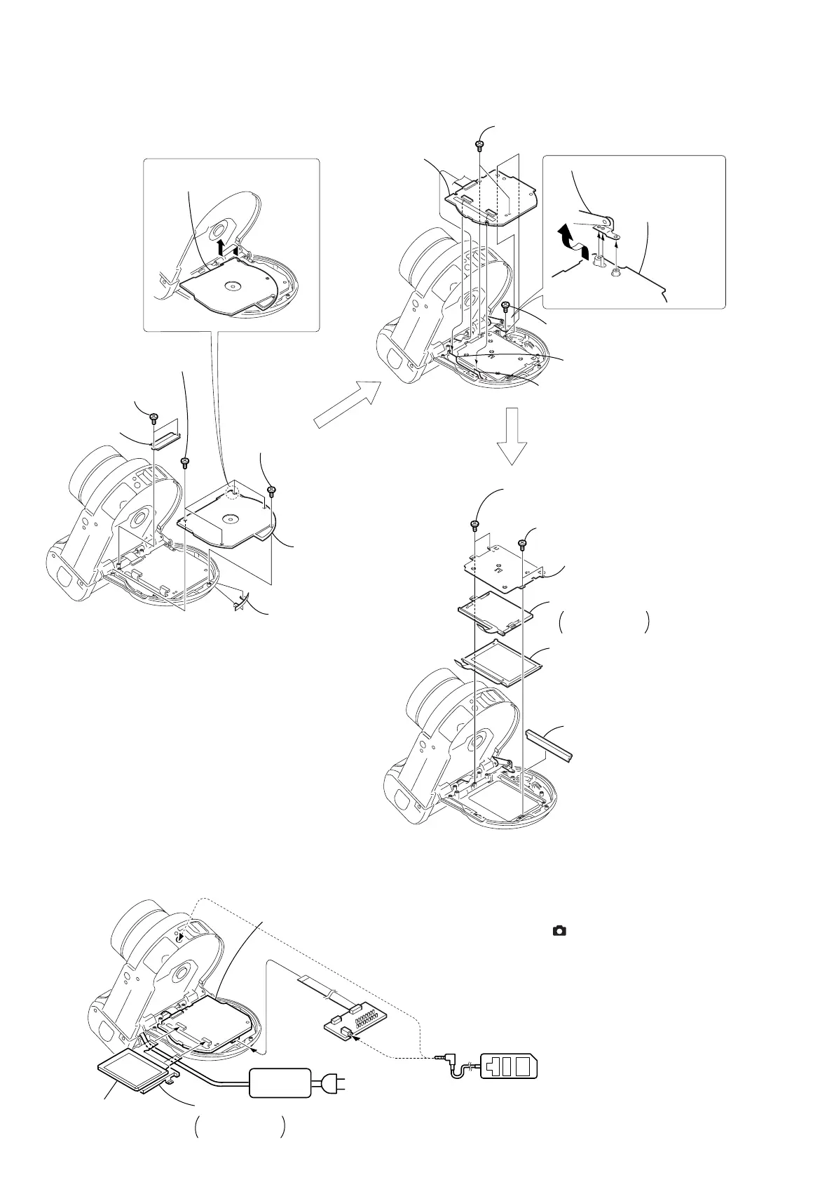
2-1. LCD SECTION (PK-58 BOARD)
NOTE: Follow the disassembly procedure in the numerical order given.
PK-58
AC power
adaptor
PK-58
PK-58
PK-58
Liquid crystal
indicator module
AC IN
Back light
Cold cathode
fluorescent tube
4 Back light
Cold cathode
fluorescent tube
CPC-9 jig
(J-6082-393-C)
18
Adjustment remote
commander ( -95)
[PK-58 BOARD SERVICE POSITION]
1
1 Two precision
screws (DIA 1.7 × 4)
3 Two precision
screws (DIA 1.7 × 4)
4 Precision
screw
(DIA 1.7 × 5)
3 Four precision
screws (DIA 1.7 × 4)
5 PK-58
board
Upper stay assembly
6 CD rear
lid
5 CPC lid
2 Flexible
cover (CD)
Remove the CD rear lid in the
direction of the arrow A.
Remove the PK-58
board in the direction
of the arrow B.
2 Two precision
screws (DIA 1.7 × 4)
1 Two precision
screws (DIA 1.7 × 4)
4 Precision
screw (DIA 1.7 × 4)
1 Liquid crystal indicator
module (24P)
5 Liquid crystal
indicator module
2 Back light
(10P)
A
B
3 BL retainer plate
6 Solar window
PK-58 board
Setup before LCD section check
To facilitate the checks, set the “Internal color bar signal” mode
using the adjustment remote control before LCD section check.
Setting the “Internal color bar signal” mode.
1) Set the mode dial to “ ”.
2) Select page: 4, address: F1, and set data: 04.
Note: If “CLOCK SET” display appered in the screen, cancel it.
Exiting the “Internal color bar signal” mode.
1) Select page: 4, address: F1, and set data: 00.

 Loading...