2-12
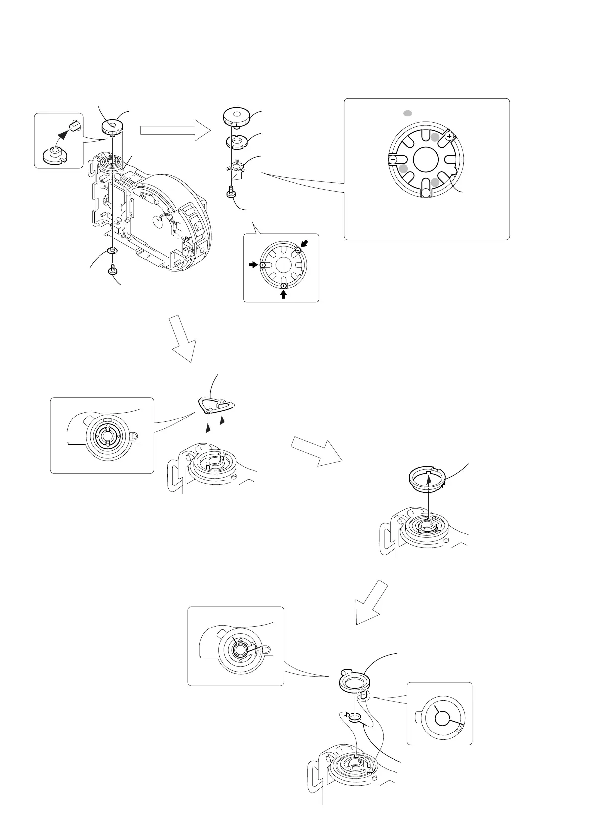
2-13.MODE KNOB, POWER SPRING
3 Mode knob
retainer
1 Special head screw
(M 1.7 × 3)
0 Power knob
9 Slider ring
qa Power spring
Rear view
Rear view
When attaching it, coat the
hatched portion with grease.
8 Friction spring
7 Mode knob
5 Click plate
Click
plate
Note: Perform the running-in rotation of the
click plate several times.
6 Dial base
4 Three EG grip
screws (M 1.4 × 2.5)
2
s
"S" position set in live A
A

 Loading...