5-31
1-6.SYSTEM CONTROL SYSTEM ADJUSTMENT
1. Battery End Adjustment (SY-67 board)
Check the battery end voltage.
Mode Still (Auto ( ))
Subject All black
(Cover the lens with a black cap)
Measurement Point Display data of page: 2, address: 9A
Measuring Instrument Adjustment remote commander
Adjustment Page D
Adjustment Address 90 to 94, B6, B7
Note1: Use the CPC-9 jig for connecting the adjustment remote
commander.
Switch setting:
FOCUS.................................................................. MANUAL
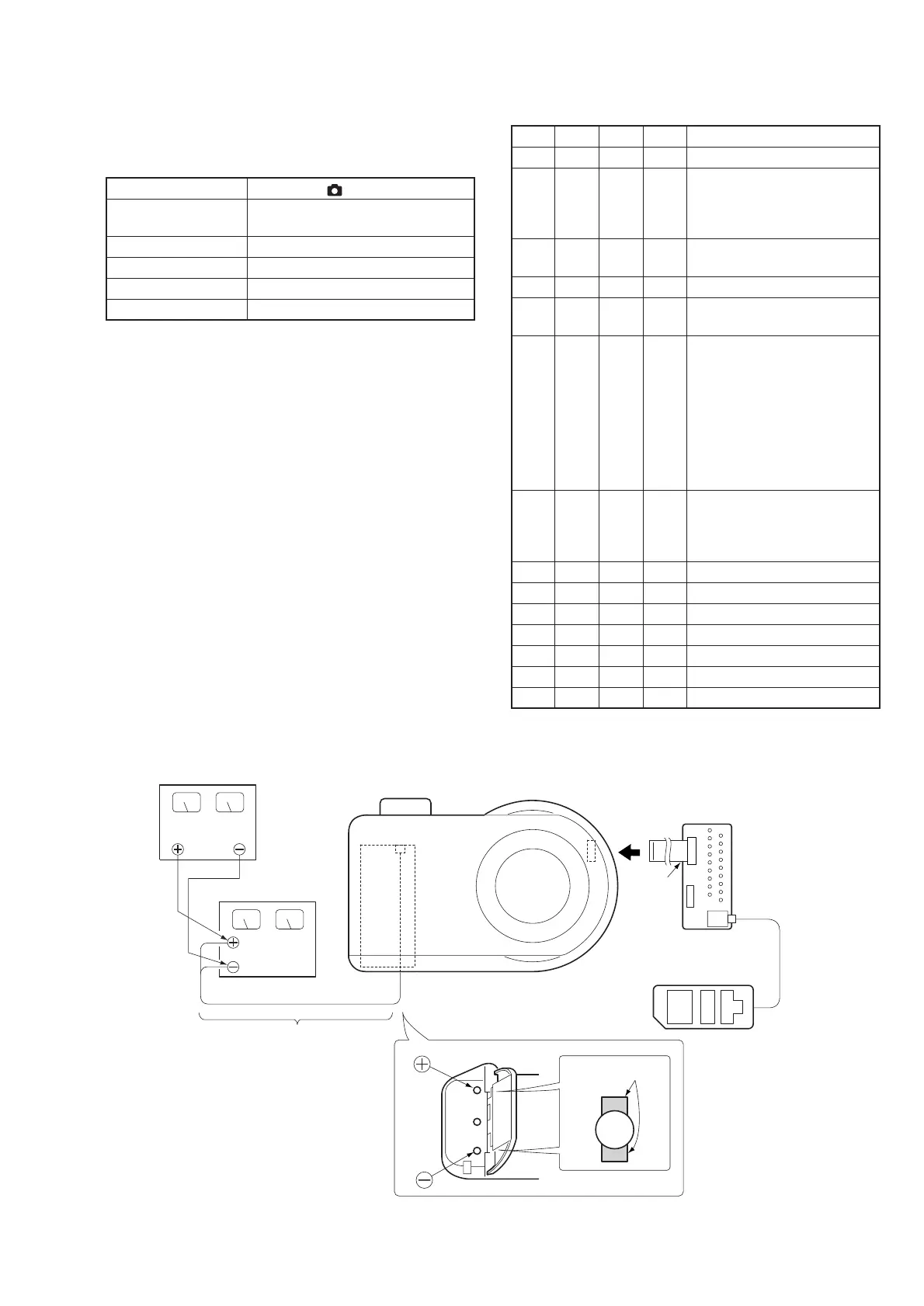
Connection:
1) Connect the regulated power supply and the digital voltmeter
to the battery terminal as shown in Fig. 5-1-23.
Preparations:
1) Adjust the output voltage of the regulated power supply so that
the digital voltmeter display is 6.1 ± 0.1Vdc.
2) Turn off the power supply.
3) Turn on the HOLD switch of the adjustment remote
commander.
4) Turn on the power supply.
Adjusting method:
Order Page
Address
Data Procedure
1 0 01 01 Set the data.
2 Decrease the output voltage of the
regulated power supply so that the
digital voltmeter display is 5.50 ±
0.01Vdc.
2 2 9A Read the data, and this data is
named Dref.
3 D 90 Dref
Set the data, and press PAUSE button.
4 Convert Dref to decimal notation,
and obtain Dref’. (Note2)
5 Calculate D91’, D92’, D93’, D94’,
DB6’, and DB7’ using following
equations. (decimal calculation)
D91’ = Dref’+ 5
D92’ = Dref’+ 23
D99’ = Dref’+ 44
D94’ = Dref’+ 55
DB6’ = Dref’+ 43
DB7’ = Dref’+ 14
6 Convert D91’, D92’, D93’, D94’,
DB6’, and DB7’ to hexadecimal
number, and obtain D91, D92, D93,
D94, DB6, and DB7. (Note2)
7 D 91 D91
Set the data, and press PAUSE button.
8 D 92 D92
Set the data, and press PAUSE button.
9 D 93 D93
Set the data, and press PAUSE button.
10 D 94 D94
Set the data, and press PAUSE button.
11 D B6 DB6
Set the data, and press PAUSE button.
12 D B7 DB7
Set the data, and press PAUSE button.
13 0 01 00 Set the data.
Note2: Refer to “Table 5-2-1. Hexadecimal-decimal Conversion Table”.
Fig. 5-1-23.
CPC-9 jig
(J-6082-393-C)
18 pins
PK-58
board
CN302
18
1
LANC
jack
Battery holder
Connecting point
Regulated power supply
Digital voltmeter
Use thick cables.
Shorten as much as possible.
(Bellow 20cm)
Adjustment remote
commander

 Loading...