5-29
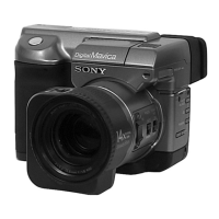
8. V-COM Level Adjustment (PK-58 board)
Set the common electrode drive signal level of LCD to the specified
value.
Mode Still (Auto ( ))
Subject Arbitrary
Measurement Point Pin 8 of CN302 (COM)
Measuring Instrument Oscilloscope
Adjustment Page D
Adjustment Address D6
Specified Value A = 6.50 ± 0.05V
Adjusting method:
Order Page
Address
Data Procedure
1 0 01 01 Set the data.
2 4 F1 03 Set the data.
3DD6
Change the data and set the V-COM
signal level (A) to the specified
value.
4 D D6 Press PAUSE button.
5 4 F1 00 Set the data.
6 0 01 00 Set the data.
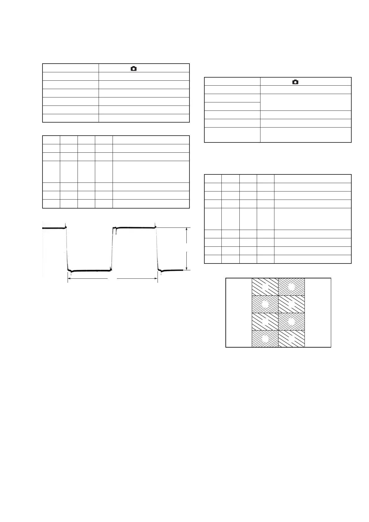
9. V-COM Adjustment (PK-58 board)
Set the DC bias of the common electrode drive signal of LCD to the
specified value.
If deviated, the LCD display will move, producing flicker and
conspicuous vertical lines.
Mode Still (Auto ( ))
Subject Arbitrary
Measurement Point Check on LCD display
Measuring Instrument
Adjustment Page D
Adjustment Address D8
Specified Value The brightness difference between the
section A and section B is minimum.
Note1: Perform “Bright Adjustment” and “Contrast Adjustment” before
this adjustment.
Adjusting method:
Order Page
Address
Data Procedure
1 0 01 01 Set the data.
2 4 F1 01 Set the data.
3 4 10 02 Set the data.
4 D D8 Change the data so that the
brightness of the section A and
that of the section B is equal.
5 D D8 Press PAUSE button.
6 4 10 00 Set the data.
7 4 F1 00 Set the data.
8 0 01 00 Set the data.
Fig. 5-1-21.
Fig. 5-1-22.
2H
A
A
A
A
A
B
B
B
B

 Loading...