26
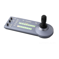
Connection with a video switcher
By connecting the tally output of a video switcher to the GPI I/O connector of the unit, the tally input
lamps of the unit light up in unison with the switcher operation which you can use to switch the target
camera to control.
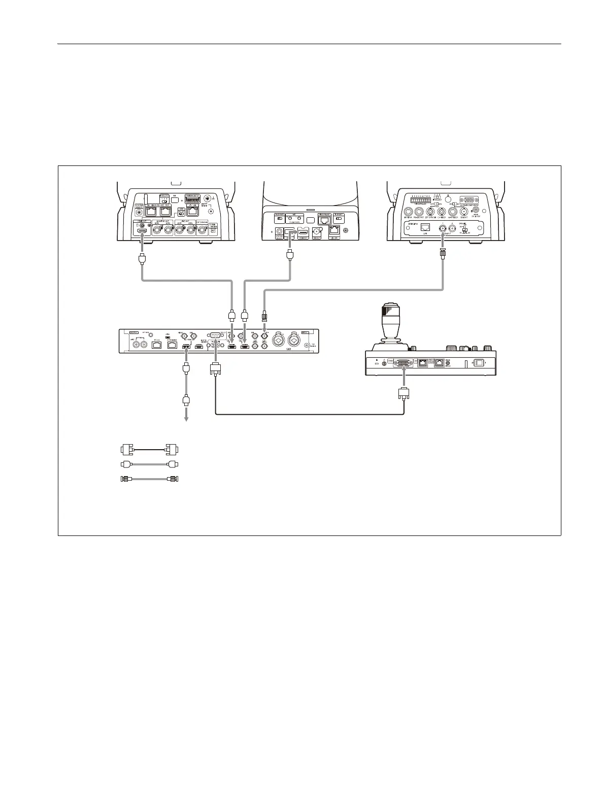
The following diagram shows the connection with an MCX-500 Multi-Camera Live Producer as an
example.
Connection example
BRC-X1000,
BRC-H800
SRG-360SHE BRC-H900
Video signal Video signal
Video signal
MCX-500
Multi-Camera Live Producer
To video monitor
Tally signal
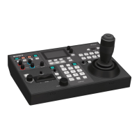
RM-IP500
Tally/contact signal: Connection cable
*1
Video signal: HDMI cable
Video signal: Connection cable with BNC connectors
*1 Use a connection cable designed for the switcher being used. For the specifications of the GPI I/O
connector of the unit, see “Pin assignments” (page 83).
 Loading...