EasyManua.ls Logo

Sony RM-IP500 User Manual

Sony RM-IP500
86 pages
To Next Page IconTo Next Page
To Previous Page IconTo Previous Page
Page #76 background imageLoading...
Page #76 background image
76
LAN
Configures the network of the unit when the unit
and target cameras are connected by LAN
connection.
For details, see “Setting the IP address of the
unit” (page 15).
SERIAL
Configures serial connections when the unit and
target cameras are connected by serial
connection.
For details, see “Configuring a serial connection”
(page 25).
CONTROL I/F
Displays the enabled control interface of
cameras.
When LAN connection is enabled, LAN is
d
isplayed. When serial connection is enabled,
SERIAL is displayed.
AUTO IP SETUP
This menu is used to configure the automatic
assignment of IP addresses of the detected
cameras on the network.
This is used when the unit and cameras are
c
onnected by LAN connection.
SETUP IP
Assigns IP addresses to cameras automatically,
and then assign the cameras to the camera
selection buttons of the unit.
For details, see “Assignment using AUTO IP
SETUP >SETUP IP” (page 18).
ASSIGN CAM
Assigns cameras that already have configured IP
addresses to the camera selection buttons of the
unit.
For details, see “Assignment using AUTO IP
SETUP >ASSIGN CAM” (page 19).
CLEAR TABLE
Clears the camera information.
For details, see “To clear the camera table”
(page 20).
SWAP CAM
Swaps the camera number and camera
information of two cameras registered in the
camera table.
For details, see “To swap camera numbers”
(page 20).
MANUAL
Used to change the group number, camera
number, and IP address assigned to a camera or
clear the camera registration manually.
For details, see “Changing the camera
registration and settings manually” (page 21).
CAMERA
LINK
setting
Control
la
mps
SETTING setting
IN OUT
OFF Tally input
lam
ps 1 to 10
Displays the
tally input
lamp
correspondin
g to the
number of
the camera
with tally
input ON.
Not lit
Camera tally
lam
p
The camera tally lamps are
not controlled. A tally lamp
ON/OFF command is not
sent.
ON Tally input
lam
ps 1 to 10
Displays the
tally input
lamp
correspondin
g to the
number of
the camera
with tally
input ON.
Not lit
Camera tally
lam
p
Displays the
camera tally
lamp
correspondin
g to the
number of
the camera
with tally
input ON.
The tally
la
mp of the
target
camera
becomes the
control
target, and
the camera
tally lamp
lights up.

Table of Contents

Question and Answer IconNeed help?

Do you have a question about the Sony RM-IP500 and is the answer not in the manual?

Sony RM-IP500 Specifications

General IconGeneral
InterfaceWired
Product colorBlack
Brand compatibilitySony
Remote control proper use-
Quantity per pack1 pc(s)
Storage temperature (T-T)-20 - 60 °C
Operating temperature (T-T)0 - 40 °C
Built-in displayYes
Maximum range- m
I/O portsRJ-45, D-Sub 15-pin, DC
RechargeableNo
Harmonized System (HS) code85299097
Weight and Dimensions IconWeight and Dimensions
Depth224.1 mm
Width306 mm
Height159.3 mm
Weight2400 g

Summary

Introduction and Features

Safety Regulations

Important points for safe unit operation.

Operating Instructions

Describes unit parts, installation, connection, and operation.

Panel Sheet for ILME-FR7

Panel sheet with function names for ILME-FR7 camera.

Product Features Overview

Highlights system construction, design, and operation capabilities.

Location and Function of Parts

Top Panel Controls

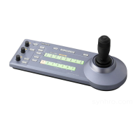
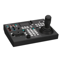
Layout and function of controls on the top panel.

Color Adjustment Block

Controls for adjusting camera color parameters.

Menu Control Block

Buttons for navigating and operating menus.

Camera Selection Block

Controls for selecting the target camera.

Lens Control Block

Controls for lens adjustments like iris, focus, and zoom.

Preset Memory Control Block

Controls for storing and recalling camera status.

Joystick Control Block

Joystick for pan, tilt, and zoom camera movements.

Rear Panel Connectors

Description of rear panel ports like LAN and power input.

Side/Front Panel Details

Information on screw holes and protective covers.

Menu Operations and Basic Navigation

RM Menu Operations

How to use the RM menu for configuration.

Camera Menu Operations

Accessing camera setup menus via the unit.

FUNCTION Menu Operations

Using shortcuts for specific function settings.

Basic RM Menu Navigation Steps

Step-by-step guide for RM menu operations.

Connection and Setup Procedures

VISCA Over IP (LAN) Connection

Setup for connecting via LAN network.

Setting the Unit's IP Address

Procedure to configure the unit's network IP address.

VISCA RS-422 Serial Connection

Setup for connecting via serial communication.

Configuring Serial Connection

Steps to set up serial communication and baud rate.

Network Configuration and Camera Management

LAN Connection Setup Example

Illustrates a typical network setup with cameras and PCs.

Assigning Cameras via AUTO IP SETUP

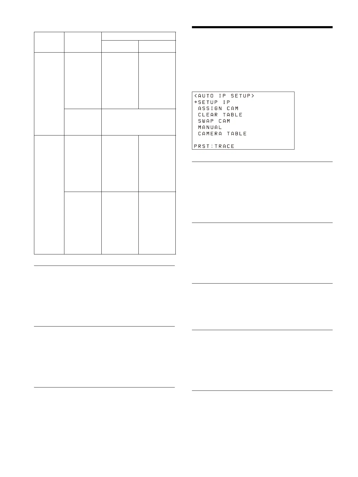
Automatic assignment of IP addresses and camera numbers.

Managing Camera Assignments

Adding, clearing, and swapping camera information.

PC Interaction and Firmware Updates

Using a Setup PC

Saving, restoring settings, and updating firmware via PC.

Accessing the Remote Controller

Procedures for backing up, restoring, and updating.

Updating the Firmware

Step-by-step process for firmware updates.

RM-IP Setup Tool Utility

Software tool for controller configuration.

General Operations and Camera Control

Powering Unit and Cameras On/Off

Procedures for turning the unit and cameras on and off.

Selecting and Controlling Cameras

Methods for selecting cameras via LAN and serial connections.

Pan, Tilt, and Zoom Camera Control

Operating camera pan, tilt, and zoom movements.

Camera Adjustments and Settings

Focus and Brightness Adjustment

Procedures for adjusting focus and brightness.

Exposure, White, and Black Balance

Adjusting exposure, white balance, and black balance.

Picture Quality Adjustments

Controls for backlight, flicker, detail, and other picture settings.

ILME-FR7 Specific Adjustments

Iris, ISO/gain, shutter, ND filter, and exposure adjustments for ILME-FR7.

Advanced Functions and Customization

Video Recording to Memory Card

Recording video clips to the camera's memory card.

Storing Camera Status (Preset Function)

Saving and recalling camera settings like position and zoom.

Trace Function: Recording Movements

Recording and playing back camera pan/tilt/zoom movements.

Assigning Functions to Buttons

Customizing buttons for specific camera functions.

Recommended ILME-FR7 Settings

Pre-configured settings for efficient operation.

Menu System and Shortcuts

Setting Specific Functions via Shortcuts (Excluding ILME-FR7)

Quick access to functions using IRIS, GAIN, SHUTTER, ASSIGN buttons.

Adjusting Detail, Knee, and Audio Level

Using ASSIGN buttons for specific parameter adjustments.

Status Checks, Maintenance, and Troubleshooting

Checking Camera Settings Status

Displaying current camera iris, gain, shutter, and zoom status.

Restoring Factory Default Settings

Resetting all unit settings to their original defaults.

Troubleshooting Common Issues

Solutions for common operational problems and symptoms.

LCD Panel Messages Guide

Explanations and remedies for warning and error messages.

Specifications and Licensing

Technical Specifications

Details on connectors, power, dimensions, and mass.

Pin Assignments Information

Pinout diagrams for RS-422 and GPI I/O connectors.

Software Licenses

Licensing terms for included software components.

Related product manuals