 Loading...
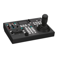
Do you have a question about the Sony RM-IP500 and is the answer not in the manual?
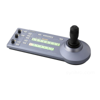
| Interface | Wired |
|---|---|
| Product color | Black |
| Brand compatibility | Sony |
| Remote control proper use | - |
| Quantity per pack | 1 pc(s) |
| Storage temperature (T-T) | -20 - 60 °C |
| Operating temperature (T-T) | 0 - 40 °C |
| Built-in display | Yes |
| Maximum range | - m |
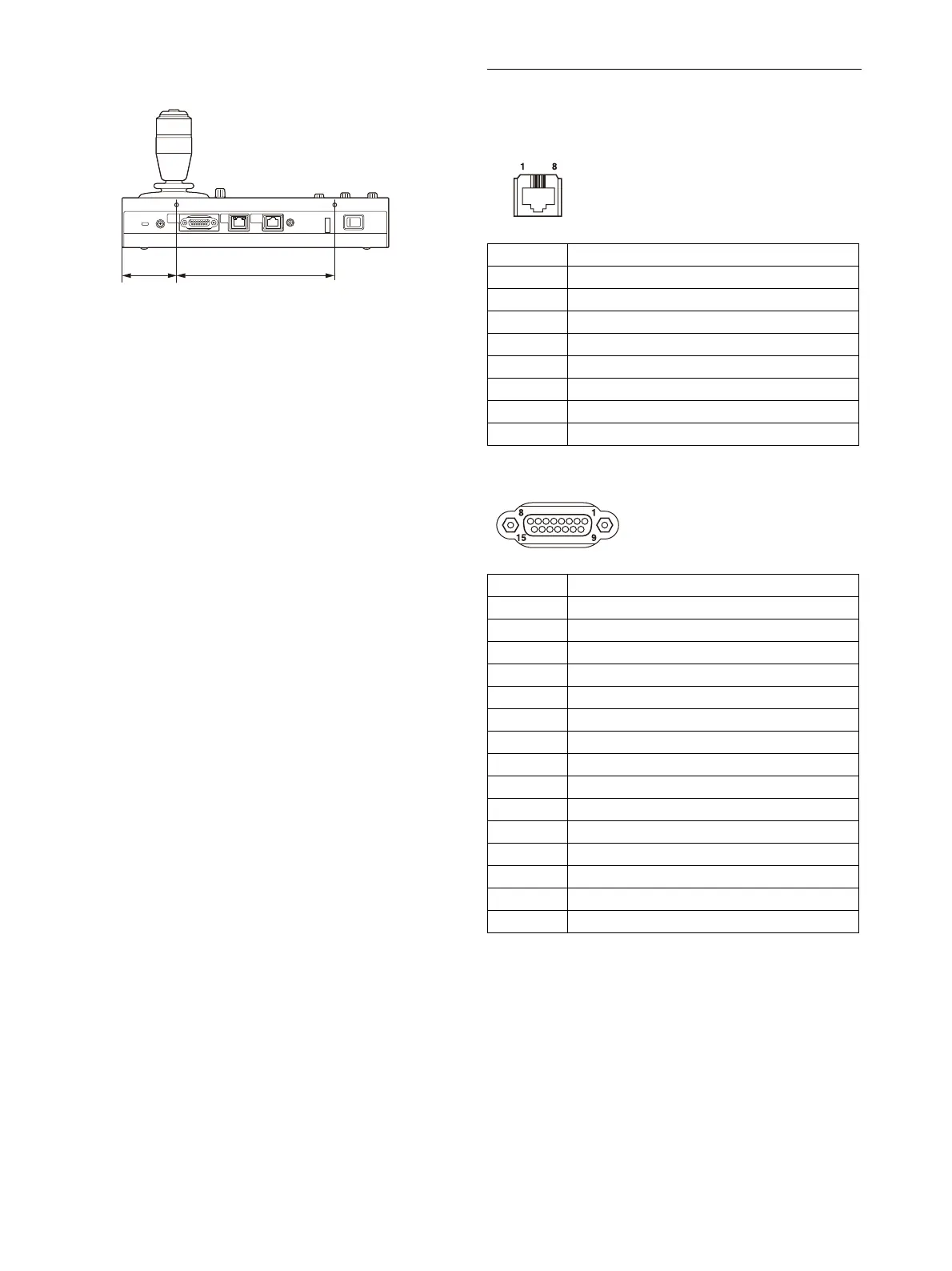
| I/O ports | RJ-45, D-Sub 15-pin, DC |
| Rechargeable | No |
| Harmonized System (HS) code | 85299097 |
| Depth | 224.1 mm |
|---|---|
| Width | 306 mm |
| Height | 159.3 mm |
| Weight | 2400 g |