1G-24 Fuel System:
• Before installing the top cap, install the new O-ring.
CAUTION
!
Replace the O-ring with a new one.
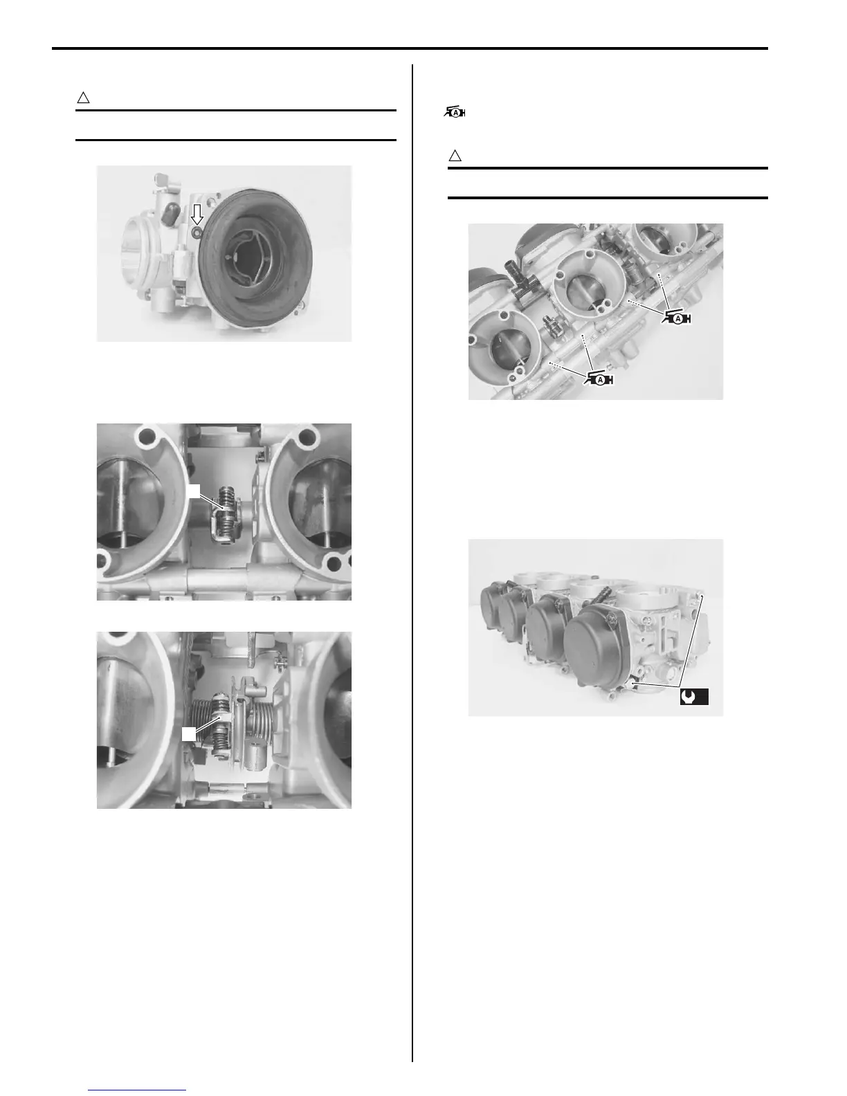
• Position the throttle valve control lever (1) between
the throttle valve synchronizing screw and spring as
shown.
• Apply thin coat of the grease to the fuel joint pipe O-
rings and seals.
: Grease 99000–25010 (SUZUKI SUPER
GREASE A or equivalent)
CAUTION
!
Replace the O-rings and seals with new ones.
• Place the carburetor assembly on the surface plate
(engine side downward) and tighten the upper and
lower carburetor set shafts to the specified torque.
Tightening torque
Carburetor set shaft (a): 5.0 N·m (0.5 kgf-m, 3.5
lb-ft)
Float Height Inspection and Adjustment
B649G11706004
Inspect and adjust the float height in the following
procedures:
1) Remove the fuel tank. Refer to “Fuel Tank Removal
and Installation: ”.
2) Remove the carburetor assembly. Refer to
“Carburetor Assembly Removal and Installation: ”.
3) Remove the float chamber. Refer to “Carburetor
Disassembly: ”.
4) To check the float height, tilt the carburetor as
shown.
I649G1170053-01
1
I649G1170054-01
1
I649G1170055-01
I649G1170056-02
(a)
I649G1170057-01

 Loading...


