1G-26 Fuel System:
2) Clean all circuits of the carburetor thoroughly – not
just the perceived problem area.
3) Clean the circuits in the carburetor body with a
spray-type cleaner and allow each circuit to soak, if
necessary, to loosen dirt and varnish.
4) Blow the body dry using compressed air.
CAUTION
!
Do not use a wire to clean the jets or
passageways. A wire can damage the jets
and passageways. If the components cannot
be cleaned with a spray cleaner it may be
necessary to use a dip-type cleaning solution
and allow them to soak.
Carburetor Heater Inspection (For E-02, 19)
B649G11706006
Carburetor Heater
1) Remove the carburetor assembly. Refer to
“Carburetor Assembly Removal and Installation: ”.
2) Disconnect the carburetor heater terminal lead
wires.
3) Connect the positive (+) terminal of a 12 V battery to
the terminal “A” of the carburetor heater and the
battery negative (–) terminal to the terminal “B”.
4) Check that the heater section “C” is heated in 5
minutes after the battery has been connected. If the
carburetor heater is not heated up, replace the
carburetor heater with a new one.
WARNING
!
Do not touch the carburetor heater directly to
prevent burn.
5) Reinstall the carburetor assembly. Refer to
“Carburetor Assembly Removal and Installation: ”.
Thermo-switch (For E-02, 19)
1) Remove the fuel tank. Refer to “Fuel Tank Removal
and Installation: ”.
2) Remove the thermo-switch. Refer to “Carburetor
Assembly Removal and Installation: ”.
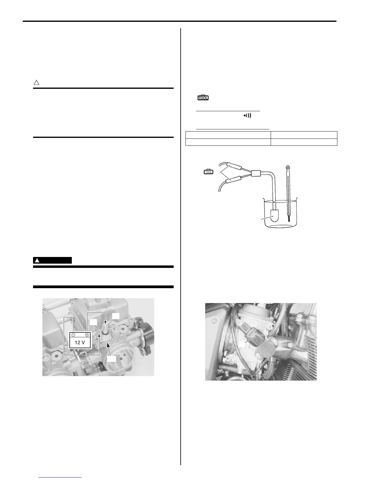
3) Cool the thermo-switch (1) with ice water and check
for continuity.
Special tool
(A): 09900–25008 (Multi-circuit tester set)
Tester knob indication
Continuity test ( )
Thermo-switch continuity
4) Install the thermo-switch.
5) Reinstall the fuel tank. Refer to “Fuel Tank Removal
and Installation: ”.
TP Sensor Inspection
B649G11706008
Inspect the TP sensor in the following procedures:
1) Disconnect the TP sensor coupler (1).
“C”
“A”
“B”
I649G1170078-01
Below 8 – 14 °CYes
Above 15 – 21 °CNo
1
(A)
I649G1170079-01
1
I649G1170065-01

 Loading...


