9C-7 Combination Meter / Fuel Meter / Horn:
Oil Pressure Switch Removal and Installation
B649G19306022
Refer to “Oil Pressure Switch Removal and Installation:
in Section 1E”.
Ignition Switch Inspection
B649G19306023
Inspect the ignition switch in the following procedures:
1) Remove the right frame head cover (GSF1200).
Refer to “Exterior Parts Removal and Installation: in
Section 9D”.
2) Disconnect the ignition switch coupler (1).
3) Inspect the ignition switch for continuity with a tester.
If any abnormality is found, replace the ignition
switch with a new one.
4) After finishing the ignition switch inspection, reinstall
the removed parts.
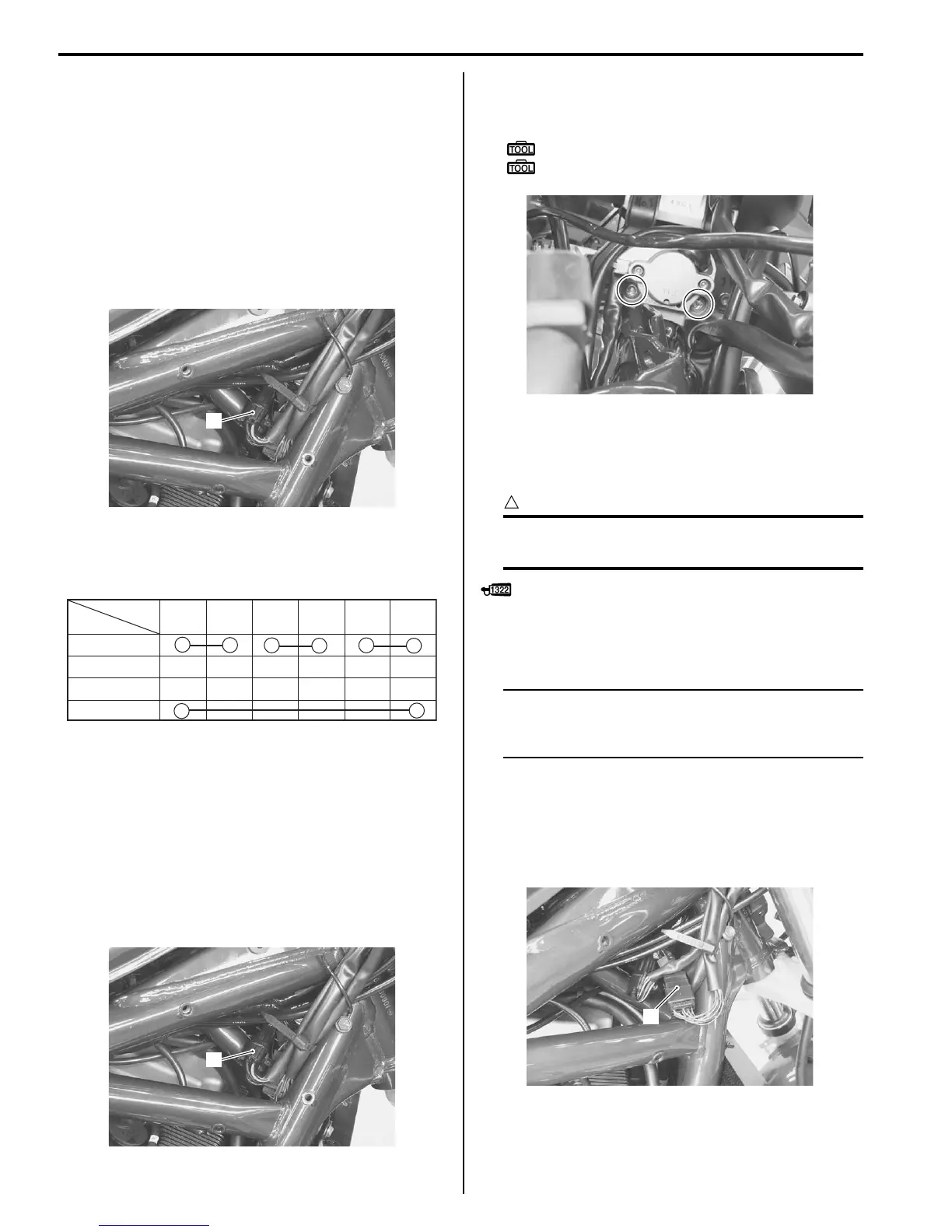
Ignition Switch Removal and Installation
B649G19306024
Removal
1) Remove the right frame head cover (GSF1200).
Refer to “Exterior Parts Removal and Installation: in
Section 9D”.
2) Disconnect the ignition switch coupler (1).
3) Remove the headlight housing (GSF1200).
4) Remove the ignition switch using the special tools.
Special tool
: 09930–11920 (Torx bit (JT 40H))
: 09930–11940 (Bit holder)
Installation
Install the ignition switch in the reverse order of removal.
Pay attention to the following point:
CAUTION
!
When reusing the ignition switch bolt, clean
thread and apply the THREAD LOCK.
: Thread lock cement 99000–32110 (Thread
Lock Cement Super 1322 or equivalent)
Horn Inspection
B649G19306026
NOTE
If the horn sound condition is normal, it is not
necessary to inspect the horn button
continuity.
Horn Button Inspection
1) Remove the right frame head cover. Refer to
“Exterior Parts Removal and Installation: in Section
9D”.
2) Disconnect the left handlebar switch coupler (1).
1
I649G1930021-01
P
LOCK
OFF
ON
B/R B/O G/B B/W B/G Br/B
Color
Position
I649G1180025-01
1
I649G1930021-01
I649G1930022-01
1
I649G1930020-01

 Loading...


