Brake Control System and Diagnosis: 4A-13
Installation
Install the rear brake master cylinder in the reverse order
of removal. Pay attention to the following points:
CAUTION
!
The seal washers should be replaced with the
new ones to prevent fluid leakage.
• Tighten the master cylinder mounting bolts (1) to the
specified torque.
• Tighten the lock-nut (2) to the specified torque.
• After setting the brake hose union to the stopper,
tighten the union bolt (3) to the specified torque.
Tightening torque
Rear master cylinder mounting bolt (a): 23 N·m (
2.3 kgf-m, 16.5 lb-ft)
Rear master cylinder rod lock-nut (b): 18 N·m (1.8
kgf-m, 13.0 lb-ft)
Brake hose union bolt (c): 23 N·m (2.3 kgf-m, 16.5
lb-ft)
• Bleed air from the system after reassembling the
master cylinder. Refer to “Brake System Inspection:
in Section 0B”.
• Adjust the brake pedal height. Refer to “Brake System
Inspection: in Section 0B”.
Rear Brake Master Cylinder Disassembly and
Assembly
B649G14106033
Refer to “Rear Brake Master Cylinder Assembly
Removal and Installation: ”.
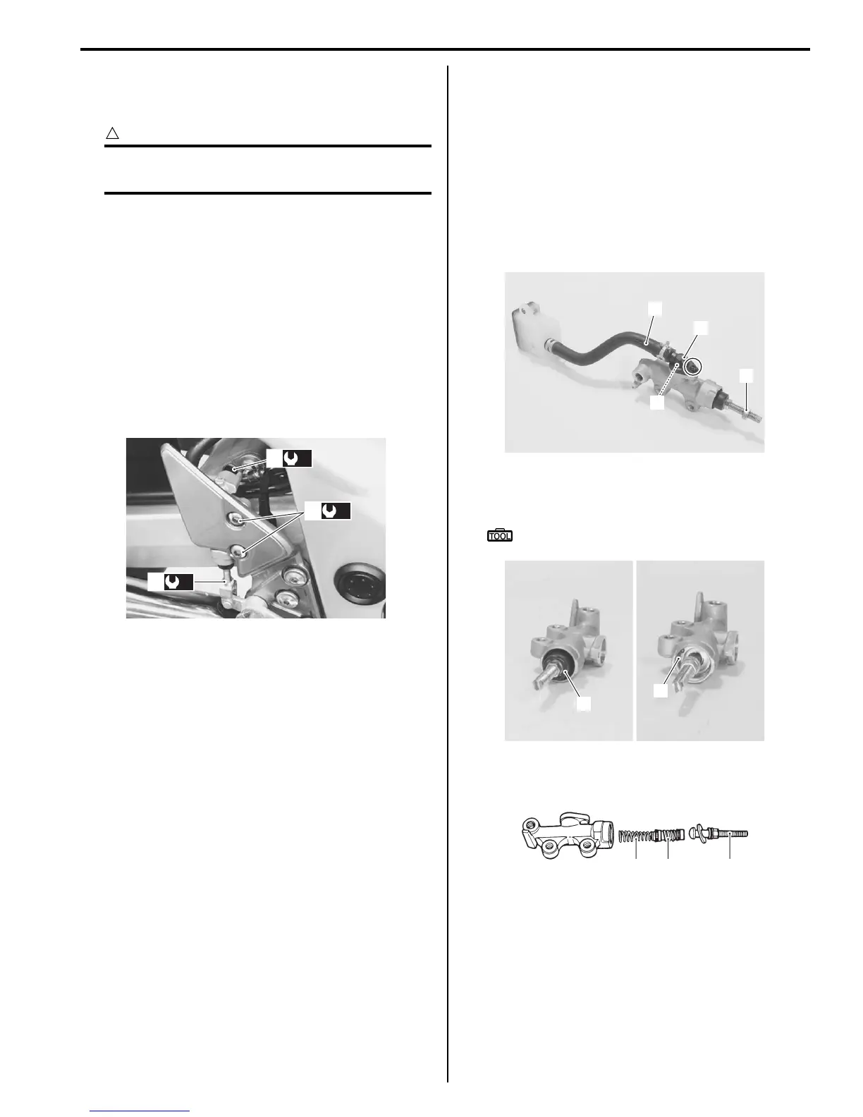
Disassembly
1) Disconnect the reservoir hose (1).
2) Remove the lock-nut (2).
3) Remove the brake hose connector (3) and O-ring
(4).
4) Pull out the dust boot (5) and remove the snap ring
(6).
Special tool
: 09900–06108 (Snap ring pliers)
5) Remove the push rod (7), piston/cup set (8) and
spring (9).
(a)
1,
(b)
2,
(c)
3,
I649G1410032-01
1
3
4
2
I649G1410033-02
5
6
I649G1410034-01
7
8
9
I649G1410035-01

 Loading...


