Ignition System: 1H-10
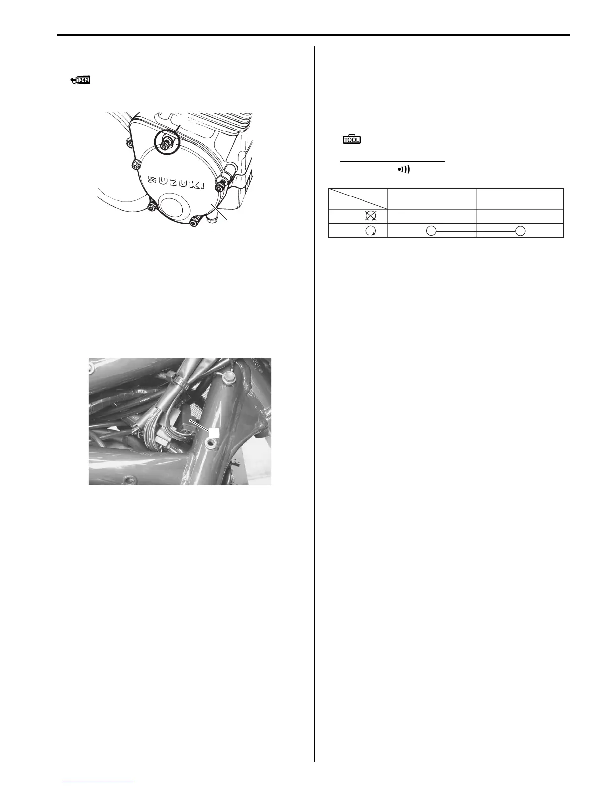
• Apply a small quantity of THREAD LOCK “1342” to
the CKP sensor cover bolts.
: Thread lock cement 99000–32050 (Thread
Lock Cement 1342 or equivalent)
Engine Stop Switch Inspection
B649G11806013
Inspect the engine stop switch in the following
procedures:
1) Remove the right frame head cover. (GSF1200)
Refer to “Exterior Parts Removal and Installation: in
Section 9D”.
2) Disconnect the right handlebar switch coupler (1).
3) Inspect the engine stop switch for continuity with a
tester.
If any abnormality is found, replace the right
handlebar switch assembly with a new one. Refer to
“Handlebars Removal and Installation: in Section
6B”.
Special tool
: 09900–25008 (Multi-circuit tester set)
Tester knob indication
Continuity ( )
4) After finishing the engine stop switch inspection,
reinstall the removed parts.
Ignition Switch Inspection
B649G11806014
Refer to “Ignition Switch Inspection: in Section 9C”.
Ignition Switch Removal and Installation
B649G11806015
Refer to “Ignition Switch Removal and Installation: in
Section 9C”.
4
3
I649G1180021-02
1
I649G1180023-02
B/BI B/R
Color
Position
OFF
RUN
()
()
I649G1180022-01

 Loading...


