Engine Mechanical: 1D-47
Valve Seat Repair
B837H11406030
The valve seats (1) for both the intake and exhaust
valves are machined to three different angles. The seat
contact surface is cut at 45°.
CAUTION
!
• The valve seat contact area must be
inspected after each cut.
• Do not use lapping compound after the
final cut is made. The finished valve seat
should have a velvety smooth finish but
not a highly polished or shiny finish. This
will provide a soft surface for the final
seating of the valve which will occur
during the first few seconds of engine
operation.
• The titanium valves are coated with an
oxidized membrane treatment to resist
wear but the membrane tend to removed if
lapped after valve seat servicing.
NOTE
After servicing the valve seats, be sure to
check the valve clearance after the cylinder
head has been reinstalled. Refer to “Valve
Clearance Inspection and Adjustment in
Section 0B (Page 0B-4)”.
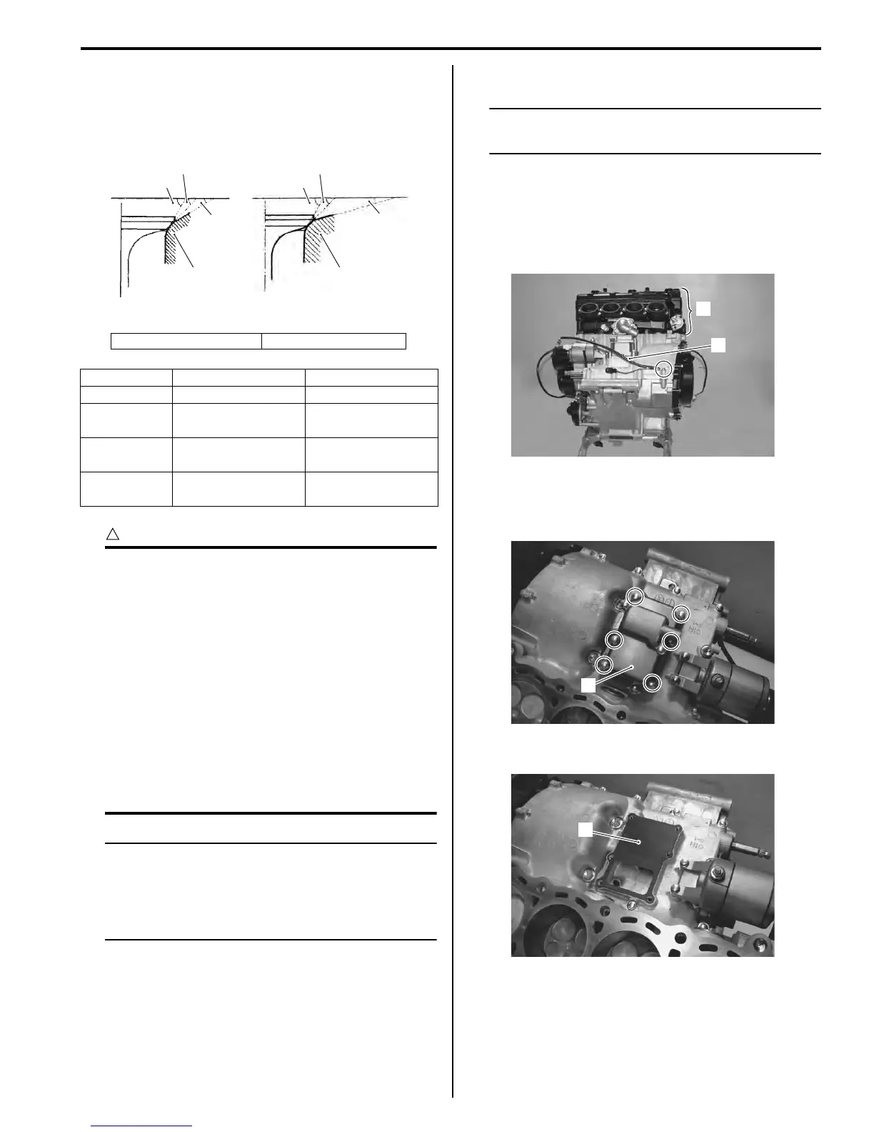
Engine Bottom Side Disassembly
B837H11406035
NOTE
The crankcase must be separated to service
the crankshaft and conrod.
1) Remove the engine assembly from the frame. Refer
to “Engine Assembly Removal (Page 1D-19)”.
2) Remove the engine top side (1). Refer to “Engine
Top Side Disassembly (Page 1D-25)”.
3) Remove the battery (–) lead wire (2).
Crankcase Breather (PCV) Cover
1) Remove the crankcase breather (PCV) cover (1).
2) Remove the gasket (2).
[A]: Intake valve [B]: Exhaust valve
Intake Exhaust
Seat angle 30°/45°/60° 15°/45°/60°
Seat width
0.9 – 1.1 mm
(0.035 – 0.043 in)
←
Valve
diameter
27.2 mm
(1.07 in)
22.0 mm
(0.87 in)
Valve guide
I.D.
4.500 – 4.512 mm
(0.1772 – 0.1776 in)
←
60q
1
45q
15q
60q
45q
30q
1
[A] [B]
I837H1140069-01
1
2
I837H1140303-01
1
I837H1140070-01
2
I837H1140071-01