1I-7 Starting System:
Starter Relay Inspection
B837H11906006
Inspect the starter relay in the following procedures:
1) Remove the starter relay. Refer to “Starter Relay
Removal and Installation (Page 1I-6)”.
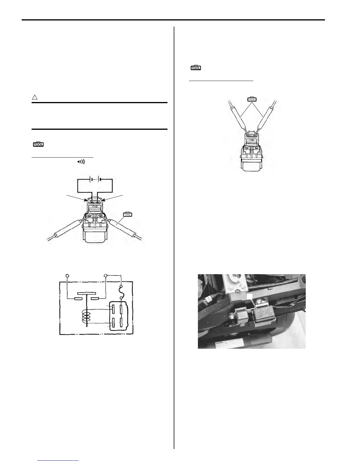
2) Apply 12 V to “A” and “B” terminals and check for
continuity between the positive and negative
terminals using the multi-circuit tester. If the starter
relay clicks and continuity is found, the relay is ok.
CAUTION
!
Do not apply battery voltage to the starter
relay for five seconds and more, since the
relay coil may overheat and get damaged.
Special tool
(A): 09900–25008 (Multi-circuit tester set)
Tester knob indication
Continuity test ( )
3) Measure the relay coil resistance between the
terminals using the multi-circuit tester. If the
resistance is not within the specified value, replace
the starter relay with a new one.
Special tool
(A): 09900–25008 (Multi-circuit tester set)
Starter relay resistance
3 – 6 Ω
4) Install the starter relay. Refer to “Starter Relay
Removal and Installation (Page 1I-6)”.
Turn Signal / Side-stand Relay Removal and
Installation
B837H11906007
Removal
1) Turn the ignition switch OFF.
2) Remove the frame cover assembly. Refer to
“Exterior Parts Removal and Installation in Section
9D (Page 9D-11)”.
3) Remove the turn signal/side-stand relay (1).
Installation
Install the turn signal/side-stand relay in the reverse
order of removal.
“A” “B”
(A)
I649G1190021-04
“A”
“B”
To batteryTo starter motor
(+)
(–)
I823H1190040-02
(A)
I649G1190023-03
1
I837H1190014-01

 Loading...


