9B-14 Lighting Systems:
Dimmer Switch Inspection
B837H19206023
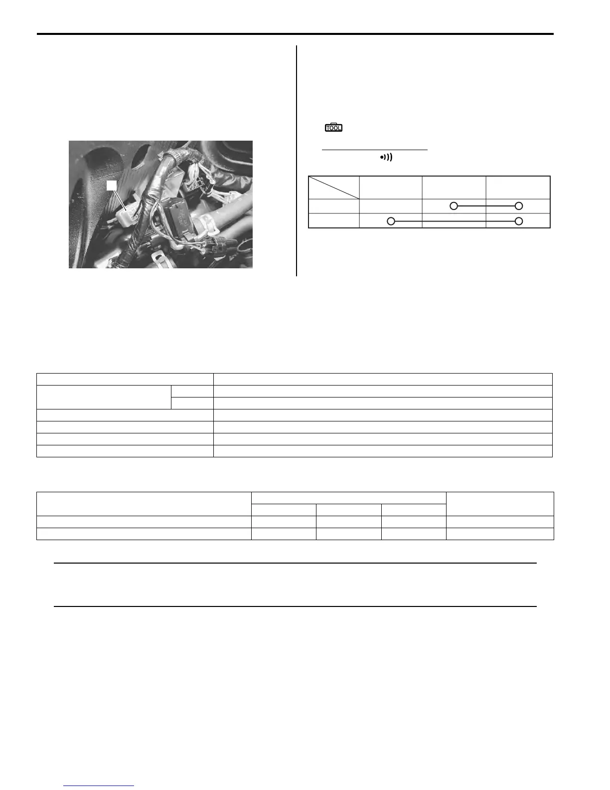
Inspect the dimmer switch in the following procedures:
1) Remove the air cleaner box. Refer to “Air Cleaner
Box Removal and Installation in Section 1D
(Page 1D-7)”.
2) Disconnect the left handlebar switch coupler (1).
3) Inspect the dimmer switch for continuity with a tester.
If any abnormality is found, replace the left
handlebar switch assembly with a new one.
Refer to “Handlebar Removal and Installation in
Section 6B (Page 6B-2)”.
Special tool
: 09900–25008 (Multi-circuit tester set)
Tester knob indication
Continuity ( )
4) After finishing the dimmer switch inspection, reinstall
the removed parts.
Specifications
Service Data
B837H19207001
Wattage
Unit: W
Tightening Torque Specifications
B837H19207002
NOTE
The specified tightening torque is also described in the following.
“Rear Lighting System Construction (Page 9B-6)”
“Reflex Reflector Construction (Page 9B-11)”
Reference:
For the tightening torque of fastener not specified in this section, refer to “Tightening Torque List in Section 0C
(Page 0C-9)”.
1
I837H1920045-01
Position
Color
WY O
HI
LO
I815H1920044-01
Item Specification
Headlight
HI 60 x 2
LO 55
Position light 5
Brake light/Taillight LED
Turn signal light 21 x 4
License plate light 5
Fastening part
Tightening torque
Note
N⋅mkgf-mlb-ft
Combination light mounting bolt 2.8 0.28 2.0 )(Page 9B-7)
License plate light mounting nut 5 0.5 3.5 )(Page 9B-9)
 Loading...


