Engine Mechanical: 1D-73
Conrod Crank Pin Bearing Removal and
Installation
B837H11406044
Refer to “Engine Bottom Side Disassembly (Page 1D-
47)”.
Refer to “Engine Bottom Side Assembly (Page 1D-54)”.
Removal
Remove the conrod crank pin bearings (1).
NOTE
• Do not remove the bearings (1) unless
absolutely necessary.
• Make a note of where the bearings are
removed from so that they can be
reinstalled in their original positions.
CAUTION
!
When removing the bearings, be careful not
to scratch the conrods and the bearings.
Installation
When installing the bearings into the conrod cap and
conrod, be sure to install the tab “A” first, and then press
in the other opposite side of the bearing.
NOTE
Inspect and select the conrod crank pin
bearing if necessary. Refer to “Conrod Crank
Pin Bearing Inspection and Selection
(Page 1D-74)”.
Conrod and Crankshaft Inspection
B837H11406040
Refer to “Engine Bottom Side Disassembly (Page 1D-
47)”.
Refer to “Engine Bottom Side Assembly (Page 1D-54)”.
Conrod Small End I.D.
Measure the conrod small end inside diameter using the
small bore gauge.
If the conrod small end inside diameter exceeds the
service limit, replace the conrod.
Special tool
(A): 09900–20602 (Dial gauge (1/1000 mm, 1
mm))
(B): 09900–22401 (Small bore gauge (10 – 18
mm))
Conrod small end I.D.
Service limit: 14.040 mm (0.5528 in)
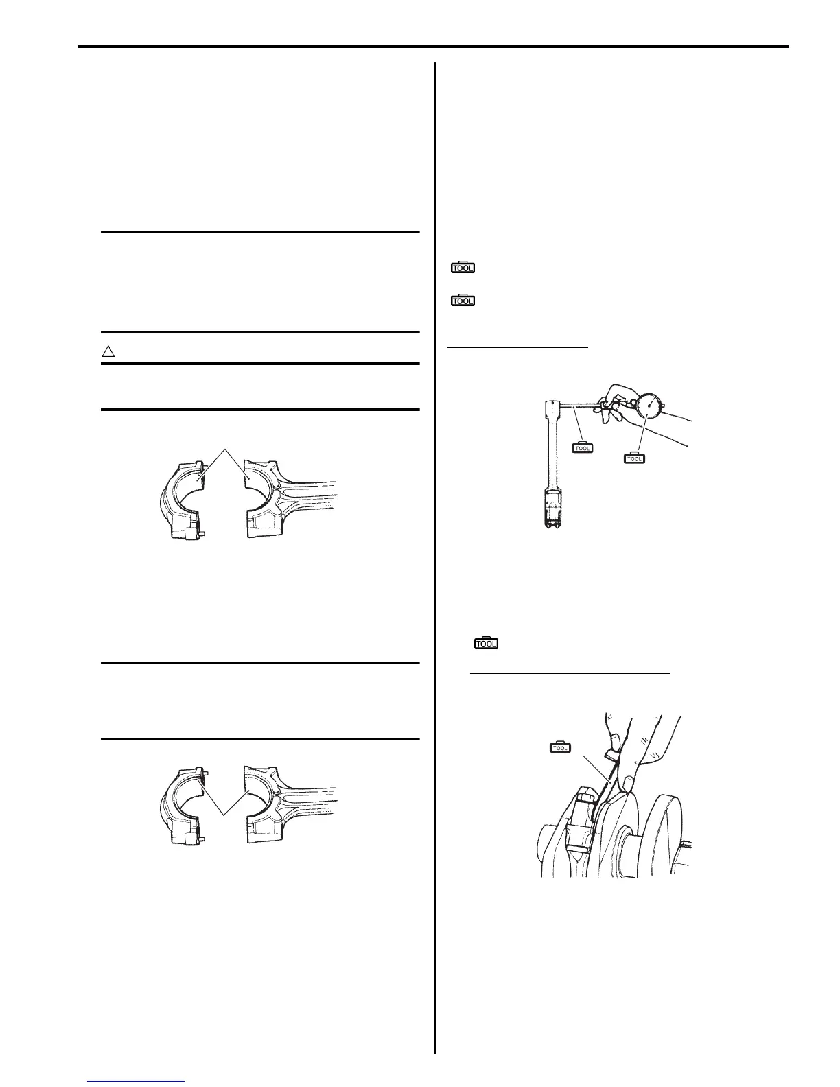
Conrod Big End Side Clearance
1) Check the conrod big end side clearance using the
thickness gauge.
Special tool
(A): 09900–20803 (Thickness gauge)
Conrod big end side clearance
Service limit: 0.3 mm (0.012 in)
1
I718H1140269-01
“A”
I823H1140578-01
(B)
(A)
I823H1140280-01
(A)
I823H1140281-01

 Loading...


