Engine Lubrication System: 1E-9
Oil Pressure Switch Removal and Installation
B837H11506007
Refer to “Electrical Components Location in Section 0A
(Page 0A-7)”.
Removal
1) Turn the ignition switch OFF.
2) Remove the right under cowling. Refer to “Exterior
Parts Removal and Installation in Section 9D
(Page 9D-11)”.
3) Drain engine oil. Refer to “Engine Oil and Filter
Replacement in Section 0B (Page 0B-10)”.
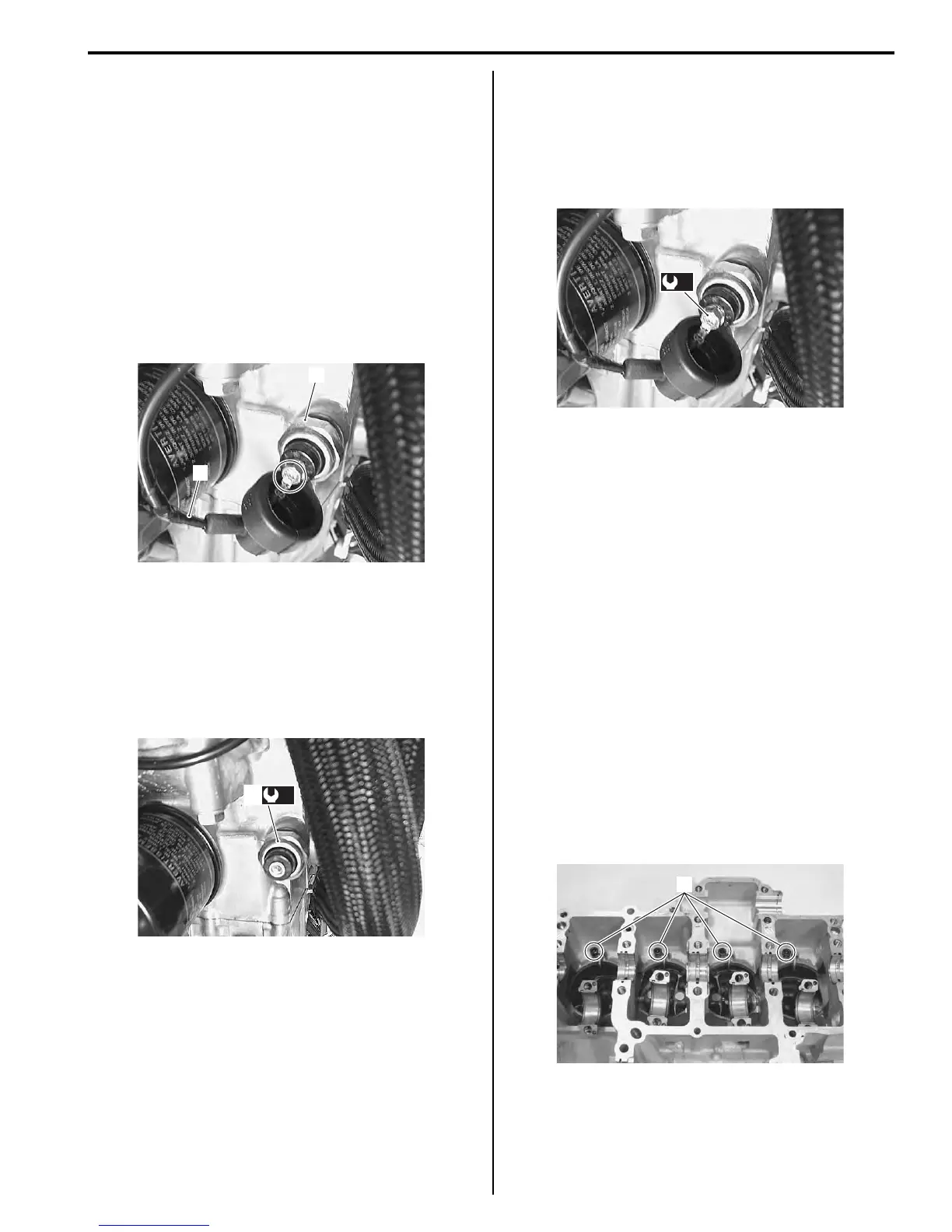
4) Disconnect the oil pressure switch lead wire (1).
5) Remove the oil pressure switch (2).
Installation
1) Install the oil pressure switch (1) and tighten it to the
specified torque.
Tightening torque
Oil pressure switch (a): 14 N·m (1.4 kgf-m, 10.0
lb-ft)
2) Connect the oil pressure switch lead wire securely.
Refer to “Wiring Harness Routing Diagram in
Section 9A (Page 9A-5)”.
Tightening torque
Oil pressure switch lead wire bolt (b): 1.5 N·m (
0.15 kgf-m, 1.1 lb-ft)
3) Pour engine oil. Refer to “Engine Oil and Filter
Replacement in Section 0B (Page 0B-10)”.
4) Install the right under cowling. Refer to “Exterior
Parts Removal and Installation in Section 9D
(Page 9D-11)”.
Oil Pressure Switch Inspection
B837H11506008
Refer to “Oil Pressure Indicator Inspection in Section 9C
(Page 9C-6)”.
Oil Jet / Oil Gallery Jet Removal and Installation
B837H11506009
Oil Jet (For Pistons)
Removal
1) Remove the engine assembly. Refer to “Engine
Assembly Removal in Section 1D (Page 1D-19)”.
2) Remove the Crankshaft assembly. Refer to “Engine
Bottom Side Disassembly in Section 1D (Page 1D-
47)”.
3) Remove the piston cooling oil jets (1) from the upper
crankcase.
1
2
I837H1150017-01
(a)
1
I837H1150018-01
(b)
I837H1150019-01
1
I837H1150020-02

 Loading...


