2C-10 Rear Suspension:
Swingarm Removal and Installation
B837H12306011
Removal
1) Cut the drive chain. Refer to “Drive Chain
Replacement in Section 3A (Page 3A-7)”.
2) Remove the rear wheel assembly. Refer to “Rear
Wheel Assembly Removal and Installation in Section
2D (Page 2D-11)”.
3) Disconnect the brake hose (1) from the brake hose
clamp.
4) Remove the brake hose clamp bolt (2).
5) Remove the brake caliper from the swingarm.
6) Remove the cushion lever (3) and rear shock
absorber (4). Refer to “Cushion Lever Removal and
Installation (Page 2C-6)” and “Rear Shock Absorber
Removal and Installation (Page 2C-3)”.
7) Remove the swingarm pivot shaft lock-nut with the
special tool.
Special tool
(A): 09940–14940 (Swingarm pivot thrust
adjuster socket wrench)
8) Hold the swingarm pivot shaft (5) and remove the
swingarm pivot nut (6).
Special tool
(B): 09944–28320 (Hexagon socket (19
mm))
9) Remove the swingarm pivot shaft.
10) Remove the swingarm assembly.
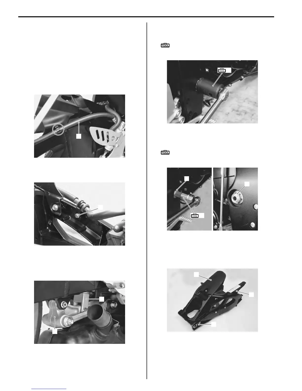
11) Remove the mudguard (7), chain case (8) and chain
buffer (9) from the swingarm.
1
I837H1230032-01
2
I837H1230033-01
3
4
I837H1230034-01
(A)
I837H1230035-01
(B)
5
6
I837H1230036-01
7
8
9
I837H1230037-01

 Loading...


