1K-7 Exhaust System:
Installation
CAUTION
!
The cable slots of EXCVA pulley must be
located adjustment position.
1) Temporarily connect the EXCV cable No. 1
(37H0CL) (1) and No. 2 (37H0OP) (2) to the EXCV
cable bracket (3) and install them to the exhaust
pipe.
NOTE
The EXCV cables are identified by the letters.
No. 1 cable (1): 37H0CL
No. 2 cable (2): 37H0OP
2) Tighten the lock-nuts (4).
3) Adjust the inner cable length “a” of No. 1 cable in 44
– 45 mm (1.73 – 1.77 in) by turning the adjuster (5),
then tighten the lock-nuts (6).
4) Turn in the adjuster (7) fully.
5) Loosen the lock-nuts (8) and turn the No. 2 cable
adjuster (9) in or out until the inner cable length “b”
becomes 60 – 61 mm (2.36 – 2.40 in).
After adjusting the inner cable length “b”, tighten the
lock-nuts (8).
6) Connect the other end of EXCV cable No. 1 (1) and
No. 2 (2) to the EXCVA pulley.
7) Install the EXCVA. Refer to “EXCVA Removal and
Installation (Page 1K-7)”.
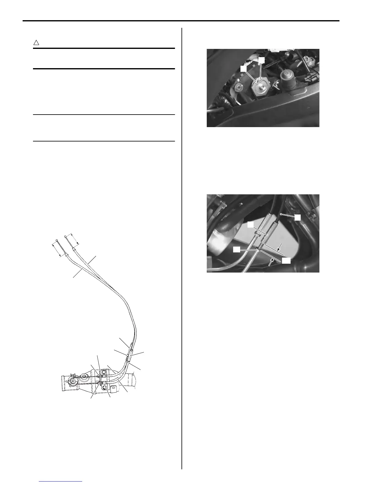
8) After connecting the No. 2 cable (2), loosen the lock-
nut (10) and turn the adjuster (7) in or out until 11 –
12 mm (0.43 – 0.47 in) of the thread length “c” on the
cable adjuster can be provided and tighten the lock-
nut (10).
9) Install the removed exterior parts.
10) Inspect the EXCVA position sensor output voltage.
Refer to “EXCVA Adjustment (Page 1K-9)”.
EXCVA Removal and Installation
B837H11B06006
Removal
1) Turn the ignition switch OFF.
2) Lift and support the fuel tank. Refer to “Fuel Tank
Removal and Installation in Section 1G (Page 1G-
9)”.
3) Remove the right under cowling assembly. Refer to
“Exterior Parts Removal and Installation in Section
9D (Page 9D-11)”.
4) Connect the special tool (Mode select switch) to the
dealer mode coupler. Refer to “Self-Diagnostic
Procedures in Section 1A (Page 1A-13)”.
“a”
“b”
4
6
7
8
9
5
1
1
2
2
3
10
I837H11B0023-04
1
2
I837H11B0024-01
2
7
“c”
10
I837H11B0025-05

 Loading...


