Combination Meter / Fuel Meter / Horn: 9C-4
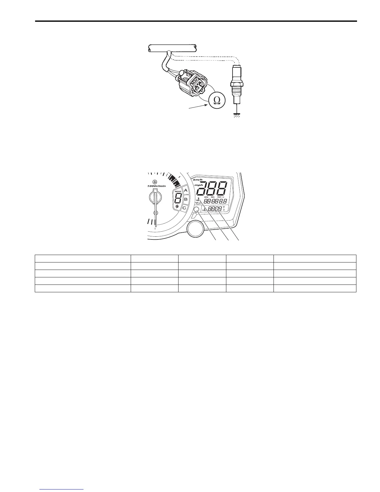
3) Connect a variable resistor (2) between the terminals.
4) Turn the ignition switch ON.
5) Check the engine coolant temperature meter (3) and indicator light (LED) (4) operations when the resistance is
adjusted to the specified values.
If either one or both indications are abnormal, replace the combination meter assembly with a new one. Refer to
“Combination Meter Removal and Installation (Page 9C-2)”.
6) Connect the ECT sensor coupler.
7) Install the removed parts.
ECT Sensor Removal and Installation
B837H19306006
Refer to “ECT Sensor Removal and Installation in Section 1C (Page 1C-4)”.
2
I718H1930009-05
Resistance “A” LED (3) LED (4) LED (5) Water temperature
2.45 kΩ and more OFF “- - -” — 19 and below
Approx. 0.318 kΩ OFF “80” — Approx. 80 °C
0.1108 kΩ and less ON “120” – “139” Flicker 120 – 139 °C
0 kΩ (Jumper wire) ON “HI” Flicker 140 °C and over
3
5
4
I837H1930008-04

 Loading...


