1I-9 Starting System:
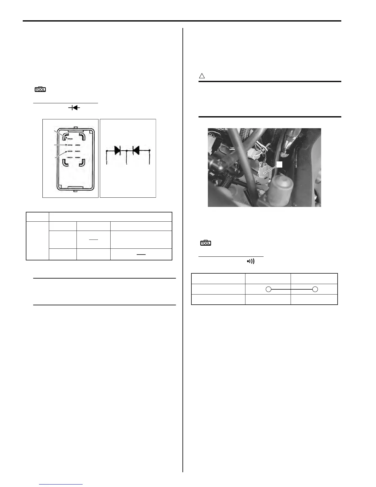
Diode inspection
1) Remove the turn signal/side-stand relay. Refer to
“Turn Signal / Side-stand Relay Removal and
Installation (Page 1I-7)”.
2) Measure the voltage between the “A”, “B” and “C”
terminals using the multi-circuit tester.
Special tool
: 09900–25008 (Multi-circuit tester set)
Tester knob indication
Diode test ( )
NOTE
If the multi circuit tester reads 1.4 V and
below when the tester probes are not
connected, replace its battery.
3) Install the turn signal/side-stand relay. Refer to “Turn
Signal / Side-stand Relay Removal and Installation
(Page 1I-7)”.
Gear Position Switch
1) Lift and support the fuel tank. Refer to “Fuel Tank
Removal and Installation in Section 1G (Page 1G-
9)”.
2) Disconnect the gear position switch coupler (1).
CAUTION
!
When disconnecting and connecting the gear
position switch coupler, make sure to turn off
the ignition switch, or electronic parts may
get damaged.
3) Check the continuity between Bl and B lead wires
with the transmission in “neutral”.
Special tool
: 09900–25008 (Multi-circuit tester set)
Tester knob indication
Continuity test ( )
4) Connect the gear position switch coupler to the
wiring harness.
5) Insert the needle pointed probes to the lead wire
coupler.
6) Turn the ignition switch ON and side-stand to upright
position.
“A”
“B”“C” “A”
“B”
“C”
I649G1190029-02
+
Probe of tester to:
“A”
“A”“C”“B”,
“C”“B”,
–0.4 0.6 V
1.4 V and more
(Tester's battery voltage)
-
Probe of
tester to:
I649G1190046-04
1
I837H1190017-01
ON (Neutral)
OFF (Except neutral)
BI B
I823H1190016-01

 Loading...


