1C-7 Engine Electrical Devices:
Installation
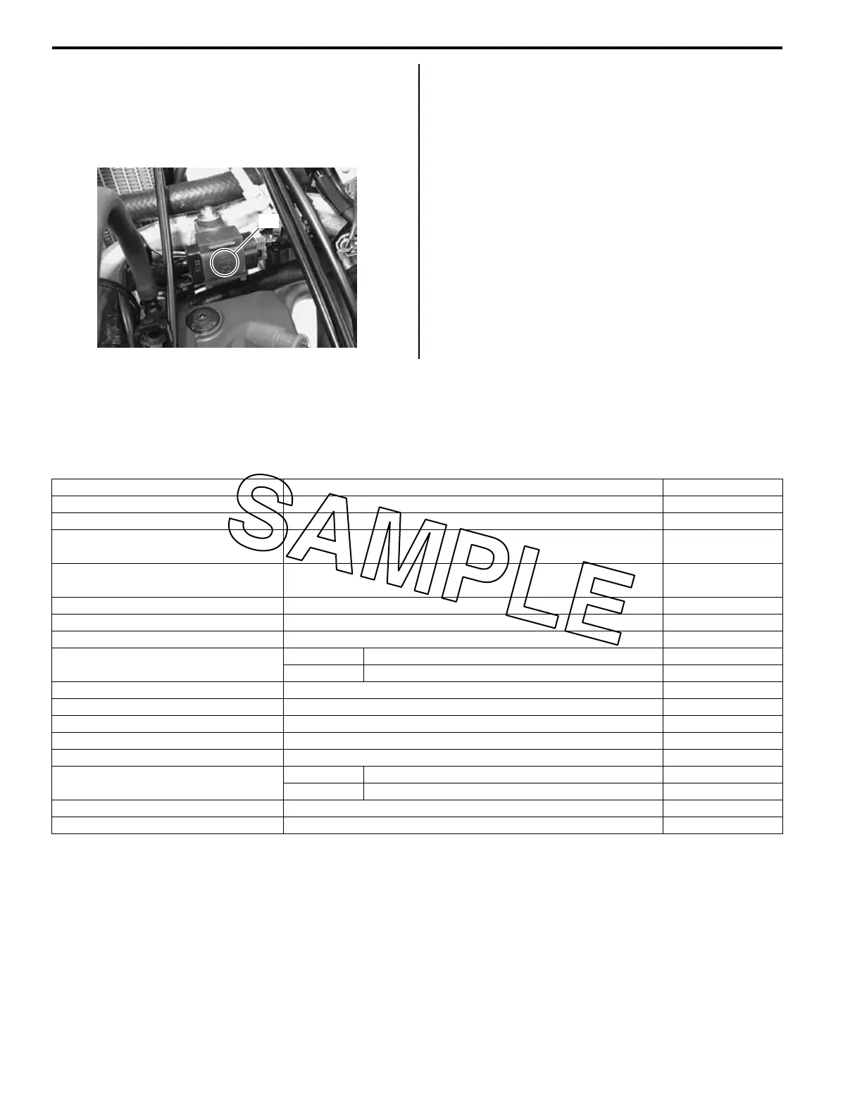
Install the TO sensor in the reverse order of removal.
Pay attention to the following points:
• When installing the TO sensor, bring the arrow mark
“A” upward.
• Install the fuel tank. Refer to “Fuel Tank Removal and
Installation” in Section 1G (Page 1G-5).
GP Switch Inspection
BA02J21306016
Refer to “Gear Position (GP) Switch Inspection” in
Section 1I (Page 1I-7).
GP Switch Removal and Installation
BA02J21306017
Refer to “Gear Position (GP) Switch Removal and
Installation” in Section 5B (Page 5B-11).
Specifications
Service Data
BA02J21307001
FI Sensors
“A”
IA02J1130019-01
Item Specification Note
CKP sensor resistance 150 – 280 Ω R – G
CKP sensor peak voltage 5.0 V and more (+): R, (–): G
Crankshaft rotation signal sensor
resistance
0.2 – 0.6 Ω B/R – R/W
Crankshaft rotation signal sensor
peak voltage
3.0 V and more (+): B/R, (–): R/W
IAP sensor input voltage 4.5 – 5.5 V
IAP sensor output voltage 0.89 – 1.17 V at idle speed
TP sensor input voltage 4.5 – 5.5 V
TP sensor output voltage
Closed Approx. 0.6 V
Opened Approx. 1.89 V
ECT sensor input voltage 4.5 – 5.5 V
ECT sensor resistance Approx. 2.58 kΩ at 20 °C (68 °F)
IAT sensor input voltage 4.5 – 5.5 V
IAT sensor resistance Approx. 2.58 kΩ at 20 °C (68 °F)
TO sensor resistance 16.5 – 22.3 kΩ
TO sensor voltage
Normal 0.4 – 1.4 V
Leaning 3.7 – 4.4 V When leaning 65°
GP switch voltage 0.6 V and more From 1st to Top
Injector voltage Battery voltage