Brake Control System and Diagnosis: 4A-7
7) Close the air bleeder valve and disconnect the clear
hose.
Tightening torque
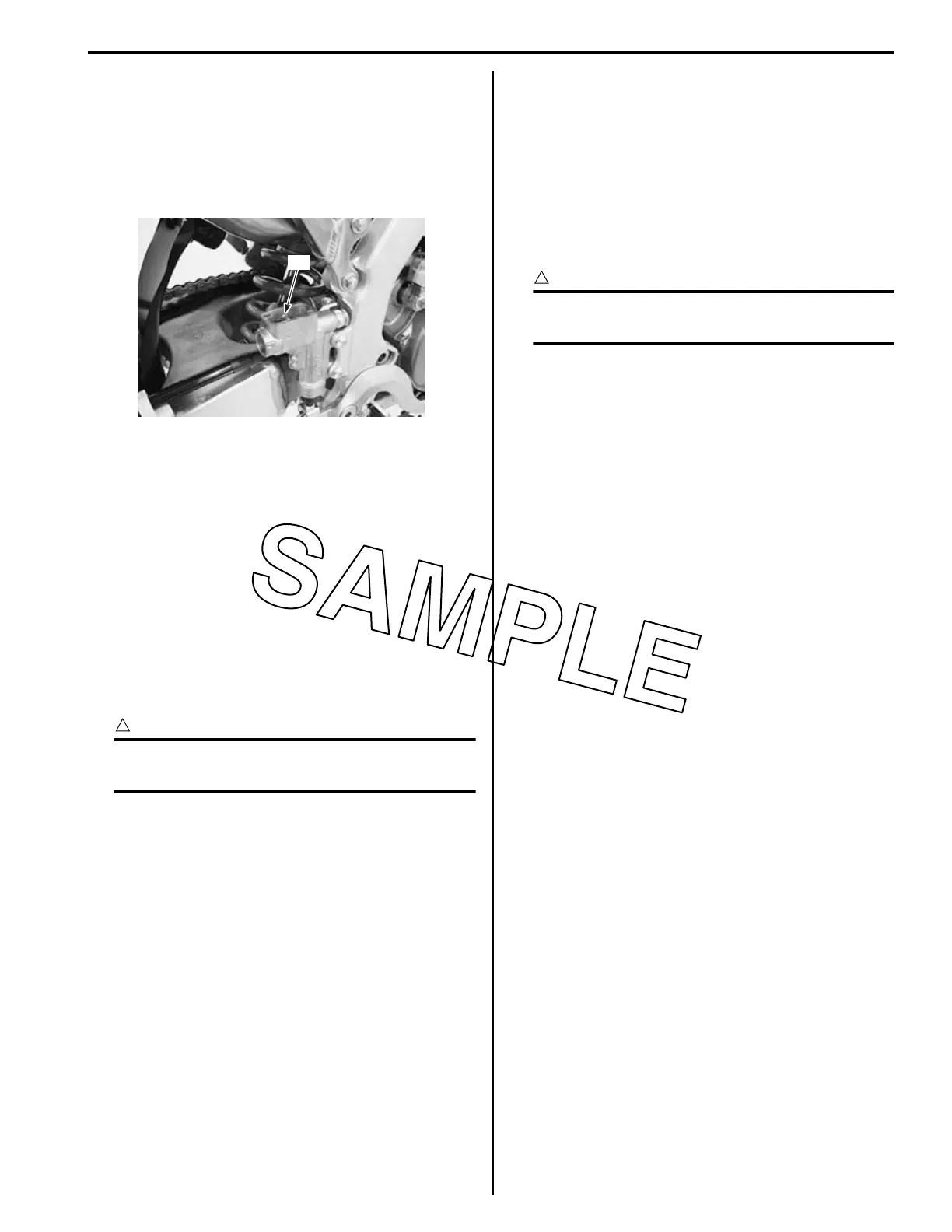
Air bleeder valve (Rear caliper): 6 N·m (0.6 kgf-
m, 4.5 lbf-ft)
8) Fill the reservoir with brake fluid to the upper line “A”.
9) Bleed air from the brake fluid circuit. Refer to “Air
Bleeding from Brake Fluid Circuit” (Page 4A-3).
10) Install the diaphragm and reservoir cap.
Front Brake Hose Removal and Installation
BA02J24106006
Removal
1) Drain brake fluid. Refer to “Brake Fluid
Replacement” (Page 4A-5).
2) Remove the front brake hoses as shown in the front
brake hose routing diagram. Refer to “Front Brake
Hose Routing Diagram” (Page 4A-1).
Installation
CAUTION
!
The seal washers should be replaced with the
new ones to prevent fluid leakage.
1) Install the front brake hose as shown in the front
brake hose routing diagram. Refer to “Front Brake
Hose Routing Diagram” (Page 4A-1).
2) Bleed air from the front brake system. Refer to “Air
Bleeding from Brake Fluid Circuit” (Page 4A-3).
Rear Brake Hose Removal and Installation
BA02J24106007
Removal
1) Drain brake fluid. Refer to “Brake Fluid
Replacement” (Page 4A-5).
2) Remove the rear brake hoses as shown in the rear
brake hose routing diagram. Refer to “Rear Brake
Hose Routing Diagram” (Page 4A-2).
Installation
CAUTION
!
The seal washers should be replaced with
new ones to prevent fluid leakage.
1) Install the rear brake hose as shown in the rear
brake hose routing diagram. Refer to “Rear Brake
Hose Routing Diagram” (Page 4A-2).
2) Bleed air from the rear brake system. Refer to “Air
Bleeding from Brake Fluid Circuit” (Page 4A-3).
“A”
IA02J1410007-01

 Loading...