Combination Meter / Fuel Meter / Horn: 9C-3
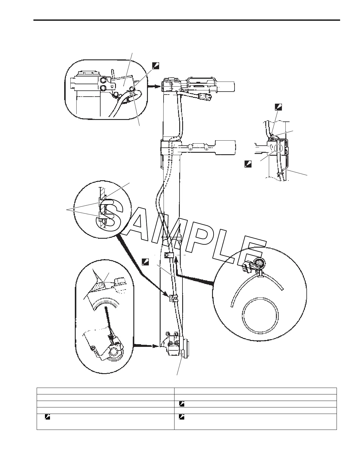
Speed Sensor Harness Routing Diagram
BA02J29306002
1
2
3
4
5
6
“D”
“C”
“A”
“B”
“C”
“D”
Outside
OutsideInside
Inside
IA02J1930013-03
1. Speed sensor 6. Ignition switch
2. Guide “A”: Stopper part of the speed sensor
3. Rivet “B”: Route the speed sensor harness tight along the fork protector.
4. Guide “C”: Marking
5. Clamp
: Cut off the excess end of clamp after binding. Face the lock
part of clamp over the lead wire.
“D”: Keep clearance between the speed sensor harness and bolt.

 Loading...