1I-7 Starting System:
4) Disconnect the starter relay lead wire coupler (1),
starter motor lead wire (2) and battery (+) lead wire
(3).
NOTE
Be sure to disconnect the starter motor lead
wire (2) first, then disconnect the battery (+)
lead wire (3).
5) Remove the starter relay (4).
Installation
Install the starter relay in the reverse order of removal.
Starter Relay Inspection
BA02J21906006
Inspect the starter relay in the following procedures:
1) Remove the starter relay. Refer to “Starter Relay
Removal and Installation” (Page 1I-6).
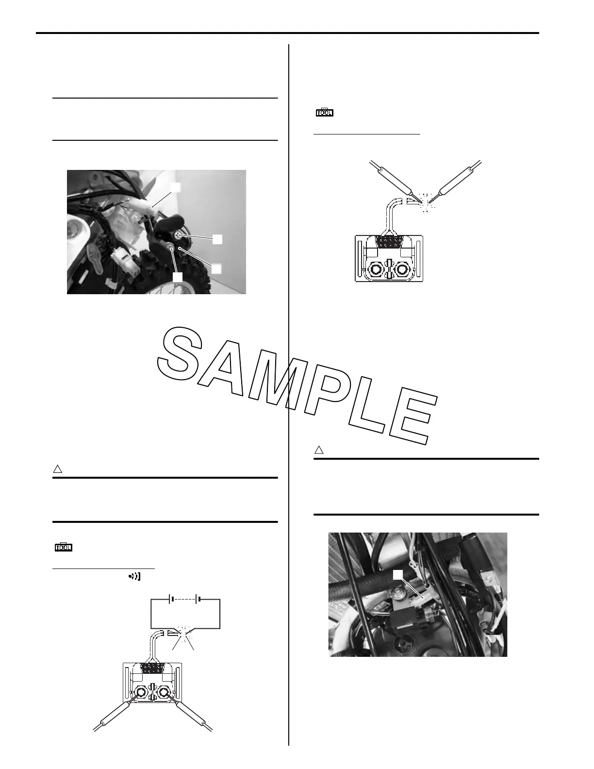
2) Apply 12 V to “A” and “B” terminals and check for
continuity between the positive and negative
terminals using the multi circuit tester. If the starter
relay clicks and continuity is found, the relay is OK.
CAUTION
!
Do not apply battery voltage to the starter
relay for five seconds and more, since the
relay coil may overheat and get damaged.
Special tool
: 09900–25008 (Multi circuit tester set)
Tester knob indication
Continuity test ( )
3) Measure the relay coil resistance between the
terminals using the multi circuit tester. If the
resistance is not within the specified value, replace
the starter relay with a new one.
Special tool
: 09900–25008 (Multi circuit tester set)
Starter relay resistance
3 – 5 Ω
4) Install the starter relay.
Gear Position (GP) Switch Inspection
BA02J21906007
Refer to “DTC “31” (P0705): GP Switch Circuit
Malfunction” in Section 1A (Page 1A-60).
Inspect the gear position switch in the following
procedures:
1) Remove the fuel tank. Refer to “Fuel Tank Removal
and Installation” in Section 1G (Page 1G-5).
2) Disconnect the gear position switch lead wire
coupler (1).
CAUTION
!
When disconnecting and connecting the gear
position switch coupler, make sure to turn off
the ignition switch, or electronic parts may
get damaged.
1
3
4
2
IA02J1190010-02
“A”
“B”
IA02J1190011-03
IA02J1190012-01
1
IA02J1190013-01

 Loading...