Ignition System: 1H-8
5) If the peak voltage is within the specification, check
the continuity between the CKP sensor/crankshaft
rotation signal sensor lead wire coupler and ECM
coupler.
CAUTION
!
Normally, use the needle-point probe to the
backside of the lead wire coupler to prevent
the terminal bend and terminal alignment.
Crankshaft Rotation Signal Sensor Resistance
1) Remove the left radiator cover. Refer to “Exterior
Parts Removal and Installation” in Section 9D
(Page 9D-1).
2) Disconnect the CKP sensor/crankshaft rotation
signal sensor lead wire coupler (1).
3) Measure the resistance between the lead wires and
ground. If the resistance is not within the standard
range, replace the stator assembly with a new one.
Refer to “CKP Sensor / Crankshaft Rotation Signal
Sensor Removal and Installation” (Page 1H-8).
Tester knob indication
Resistance (Ω)
Crankshaft rotation signal sensor resistance
0.2 – 0.6 Ω (B/R – R/W)
∞ Ω (B/R – Ground)
4) After measuring the crankshaft rotation signal sensor
resistance, reinstall the removed parts.
CKP Sensor / Crankshaft Rotation Signal
Sensor Removal and Installation
BA02J21806006
Refer to “Generator Removal and Installation” in Section
1J (Page 1J-5).
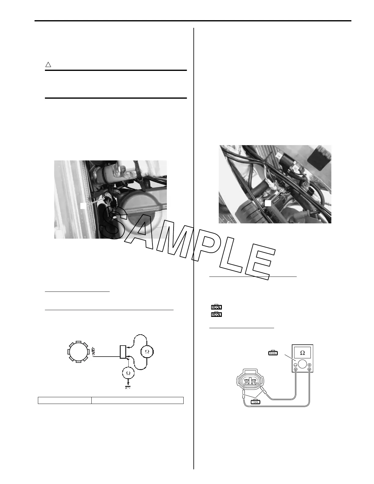
Engine Stop Switch Inspection
BA02J21806007
Inspect the engine stop switch in the following
procedures:
1) Turn off the ignition switch.
2) Remove the fuel tank. Refer to “Fuel Tank Removal
and Installation” in Section 1G (Page 1G-5).
3) Disconnect the engine stop switch lead wire coupler
(1).
4) Measure the engine stop switch resistance between
B/Y lead wire and B/W lead wire. If any abnormality
is found, replace the engine stop switch assembly
with a new one. Refer to “Handlebars Removal and
Installation” in Section 6B (Page 6B-3).
Engine stop switch resistance
ON: Under 1 Ω (B/Y – B/W)
OFF: ∞Ω (Infinity) (B/Y – B/W)
Special tool
(A): 09900–25008 (Multi circuit tester set)
(B): 09900–25009 (Needle-point probe set)
Tester knob indication
Resistance (Ω)
5) After finishing the engine stop switch inspection,
reinstall the removed parts.
1. Coupler 2. Crankshaft rotation signal sensor
1
IA02J1180007-02
2
1
IA02J1180010-01
1
IA02J1180011-01
(B)
(A)
IA02J1180019-01

 Loading...