1G-7 Fuel System:
Installation
Install the fuel pump in the reverse order of removal. Pay
attention to the following points:
• Install a new O-ring and apply grease to it.
CAUTION
!
Replace the O-ring with a new one.
: Grease 99000–25010 (SUZUKI SUPER
GREASE “A” or equivalent)
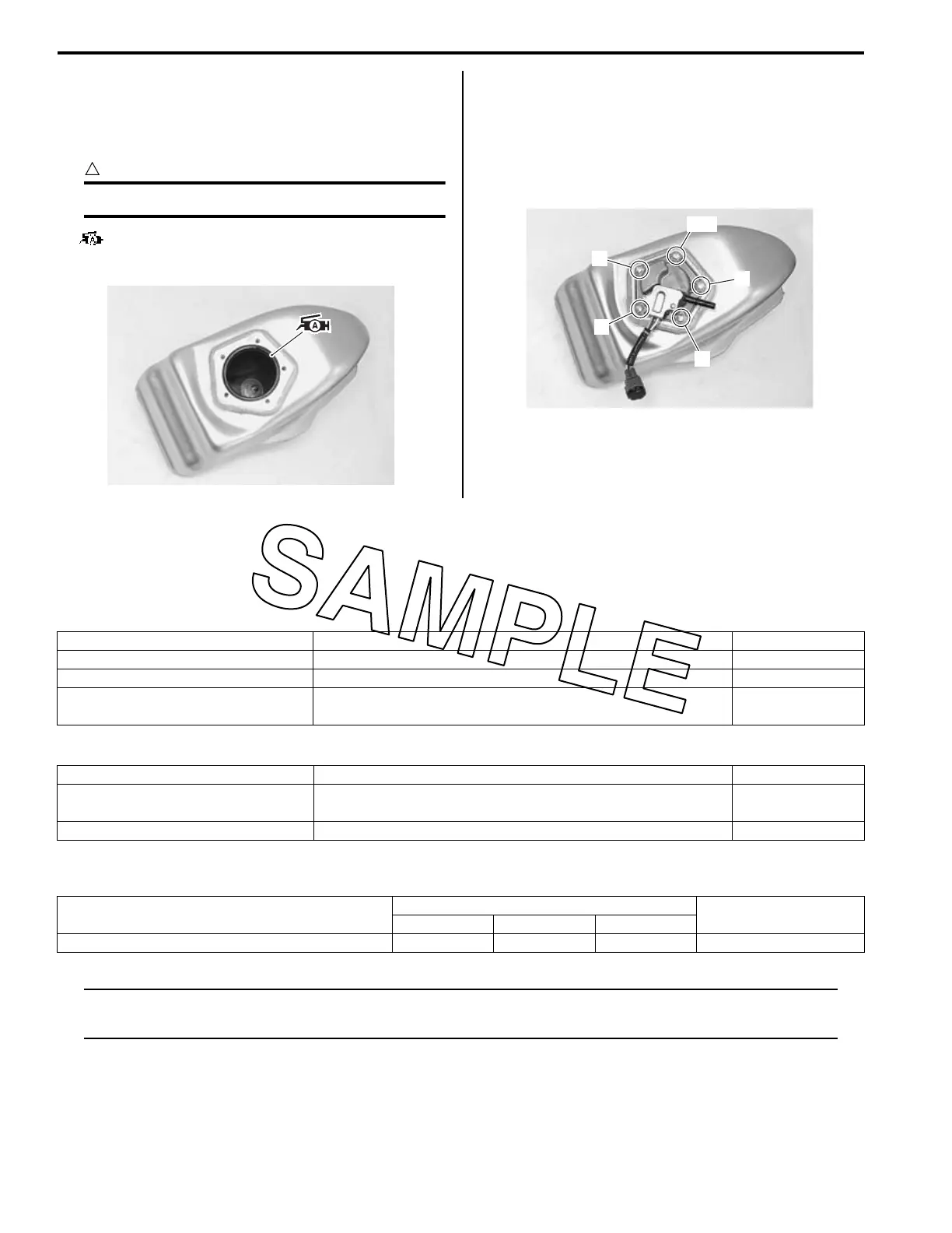
• When installing the fuel pump assembly, first tighten
all the fuel pump mounting bolts lightly and then to the
specified torque in the ascending order of numbers.
Tightening torque
Fuel pump mounting bolt: 10 N·m (1.0 kgf-m, 7.0
lbf-ft)
Specifications
Service Data
BA02J21707001
Injector + Fuel Pump + Fuel Pressure Regulator
Fuel
Tightening Torque Specifications
BA02J21707002
NOTE
The specified tightening torque is described in the following.
“Fuel Tank Components” (Page 1G-5)
Reference:
For the tightening torque of fastener not specified in this section, refer to “Tightening Torque List” in Section 0C
(Page 0C-8).
IA02J1170014-01
1, 6
3
5
2
4
IA02J1170015-01
Item Specification Note
Injector resistance 10.5 – 0.53 Ω at 24 °C (75.2 °F)
Fuel pump discharge amount Approx. 240 ml (8.1/8.4 US/lmp oz) /10 sec.
Fuel pressure regulator operating
set pressure
Approx. 294 kPa (2.94 kgf/cm
2
, 41.81 psi)
Item Specification Note
Fuel type
Use only unleaded gasoline of at least 90 pump octane (R/2
+ M/2 method).
Fuel tank capacity 6.2 L (1.6/1.4 US/lmp gal)
Fastening part
Tightening torque
Note
N⋅mkgf-mlbf-ft
Fuel pump mounting bolt 10 1.0 7.0 )(Page 1G-7)

 Loading...