9C-4 Combination Meter / Fuel Meter / Horn:
Speedometer Removal and Installation
BA02J29306003
Removal
1) Remove the battery (–) lead wire.
2) Remove the headlight cover. Refer to “Headlight
Removal and Installation” in Section 9B (Page 9B-2).
3) Disconnect the combination meter lead wire coupler
(1) and speed sensor lead wire coupler (2).
4) Remove the Speedometer (3).
Installation
Installation is in the reverse order of removal.
Speedometer Inspection
BA02J29306004
If the speedometer, odometer or tripmeter does not
function properly, inspect the speed sensor and its
coupler connections. If the speed sensor and coupler
connections are OK, replace the combination meter unit
with a new one. Refer to “Speedometer Removal and
Installation” (Page 9C-4).
Speed Sensor Removal and Installation
BA02J29306005
Refer to “Front Wheel Assembly Removal and
Installation” in Section 2D (Page 2D-3) and “Speed
Sensor Harness Routing Diagram” (Page 9C-3).
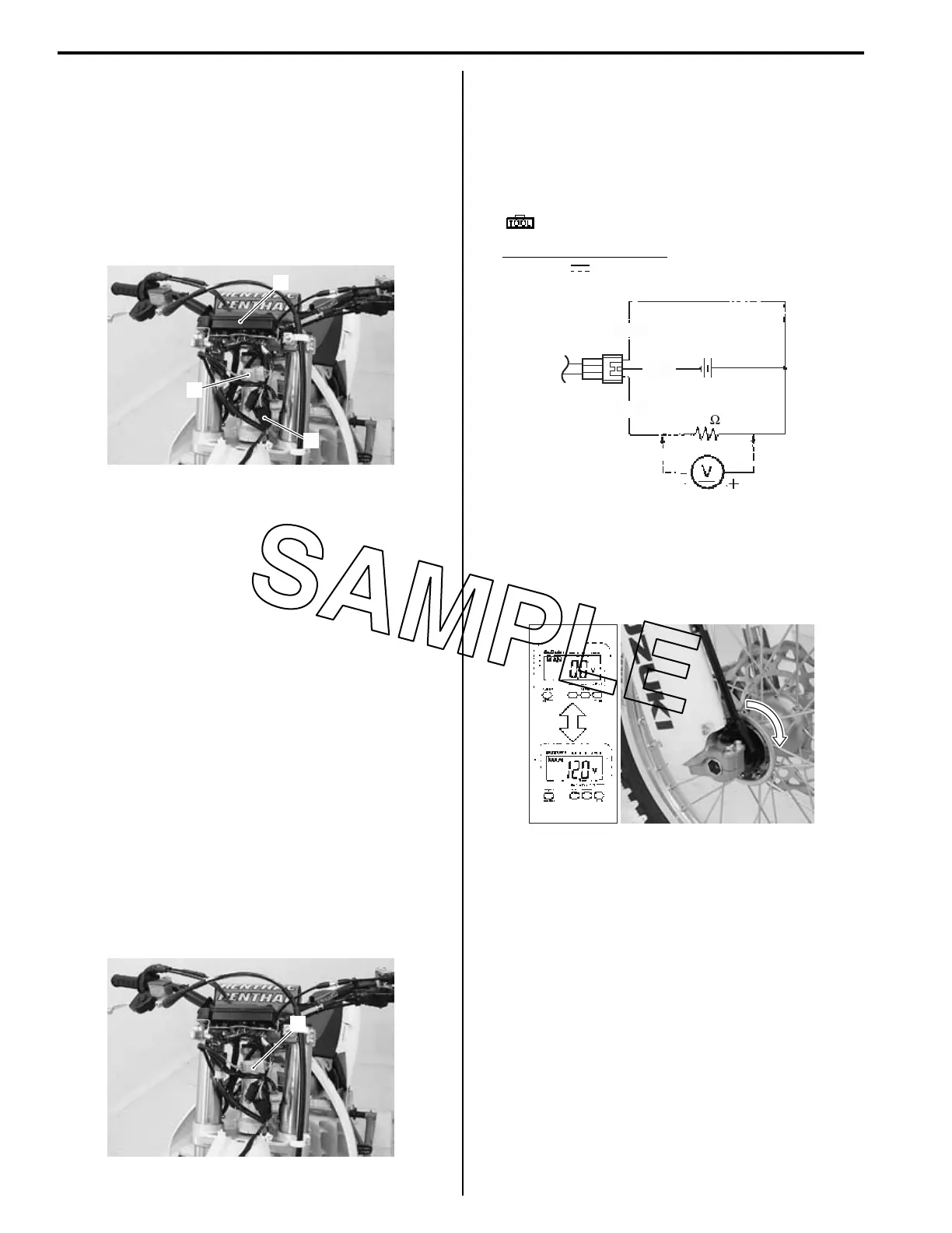
Speed Sensor Inspection
BA02J29306006
Inspect the speed sensor in the following procedures:
1) Remove the headlight cover. Refer to “Headlight
Removal and Installation” in Section 9B (Page 9B-2).
2) Disconnect the speed sensor lead wire coupler (1).
3) Raise the front wheel off the ground and support the
motorcycle with a jack or a wooden block.
4) Connect a 12 V battery (between O/R and B/W), 10
kΩ resister (between O/R and P) and multi circuit
tester (tester (+) probe to O/R and tester (–) probe to
P) as shown in the figure.
Special tool
: 09900–25008 (Multi circuit tester set)
Tester knob indication
Voltage ( )
5) Turn the front wheel and check that voltage varies
between 0 – 12 V.
If any abnormal condition is noted, replace the speed
sensor with a new one. Refer to “Speed Sensor
Removal and Installation” (Page 9C-4).
6) Install the removed parts.
1
2
3
IA02J1930002-01
1
IA02J1930003-01
O/R
12V
B/W
P
10k
IA02J1930004-01
IA02J1930005-02

 Loading...