1D-47 Engine Mechanical:
7) Drive the guide into the guide hole using the valve
guide installer.
CAUTION
!
Failure to oil the valve guide hole before
driving the new guide into place may result in
a damaged guide or head.
Special tool
(A): 09916–44310 (Valve guide remover/
installer)
(D): 09916–53360 (Attachment)
8) After installing the valve guides, refinish their guiding
bores using the reamer. Be sure to clean and oil the
guides after reaming.
Special tool
(C): 09916–34542 (Reamer handle)
(E): 09916–34550 (Valve guide reamer (5.5
mm))
NOTE
• Be sure to cool down the cylinder head to
ambient air temperature.
• Insert the reamer from the combustion
chamber and always turn the reamer
handle clockwise.
9) Reassemble the cylinder head. Refer to “Cylinder
Head Disassembly and Assembly” (Page 1D-39).
10) Install the cylinder head assembly. Refer to “Engine
Top Side Assembly” (Page 1D-30).
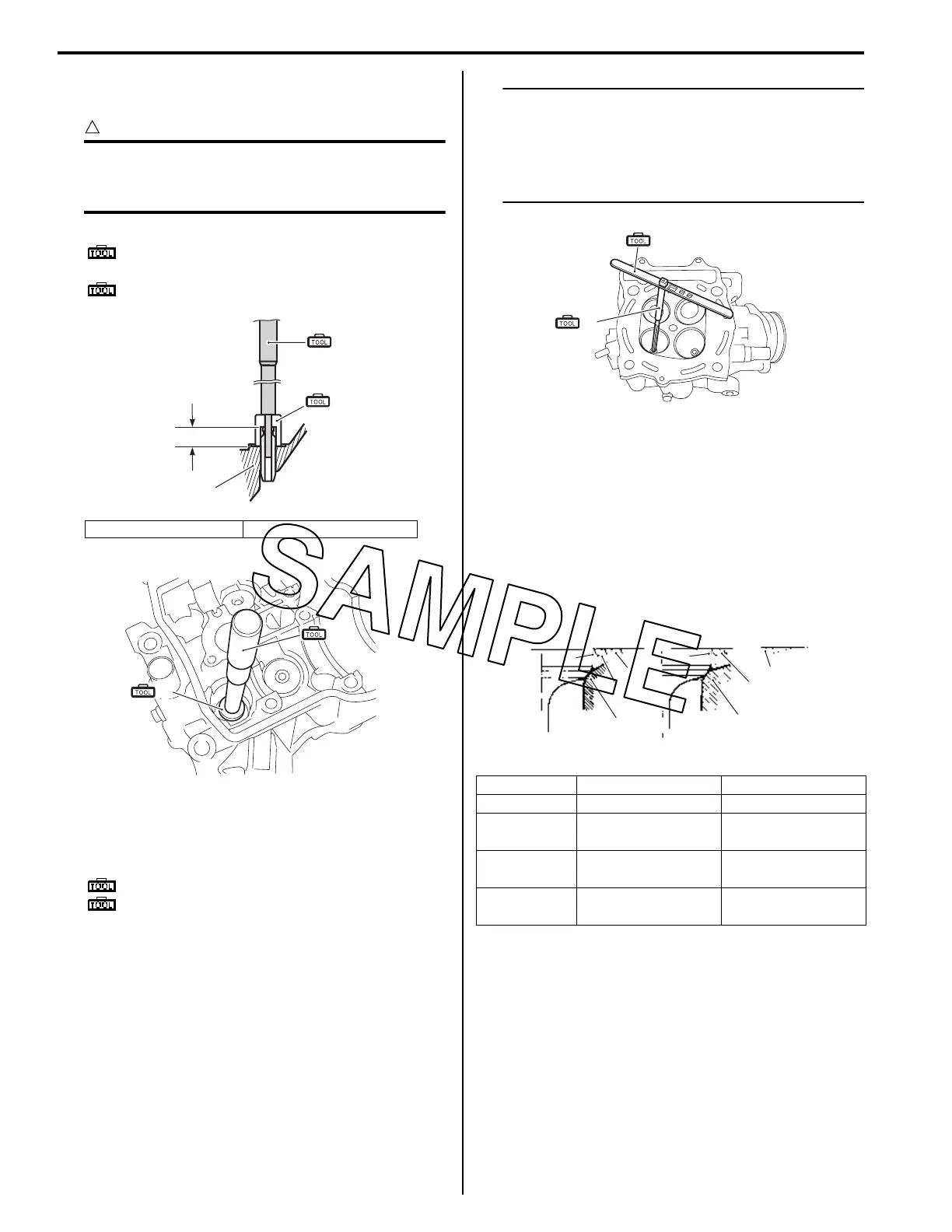
Valve Seat Repair
BA02J21406028
The valve seats (1) for both the intake and exhaust
valves are machined to three different angles. The seat
contact surface is cut at 45°.
1. Cylinder head “a”: 12.2 mm (0.48 in)
“a”
(A)
(D)
1
I718H1140127-01
(D)
(A)
IA02J1140037-01
Intake Exhaust
Seat angle 30°/45°/60° 15°/45°/60°
Seat width
0.9 – 1.1 mm
(0.035 – 0.043 in)
←
Valve
diameter
36 mm
(1.42 in)
31 mm
(1.22 in)
Valve guide
I.D.
5.500 – 5.512 mm
(0.2165 – 0.2170 in)
←
(C)
(E)
IA02J1140038-02
1
1
60°
30°
45°
15°
45°
60°
IN EX
I831G1140170-02

 Loading...