1A-11 Engine General Information and Diagnosis:
1) Remove the left frame cover. Refer to “Exterior Parts
Removal and Installation” in Section 9D (Page 9D-
1).
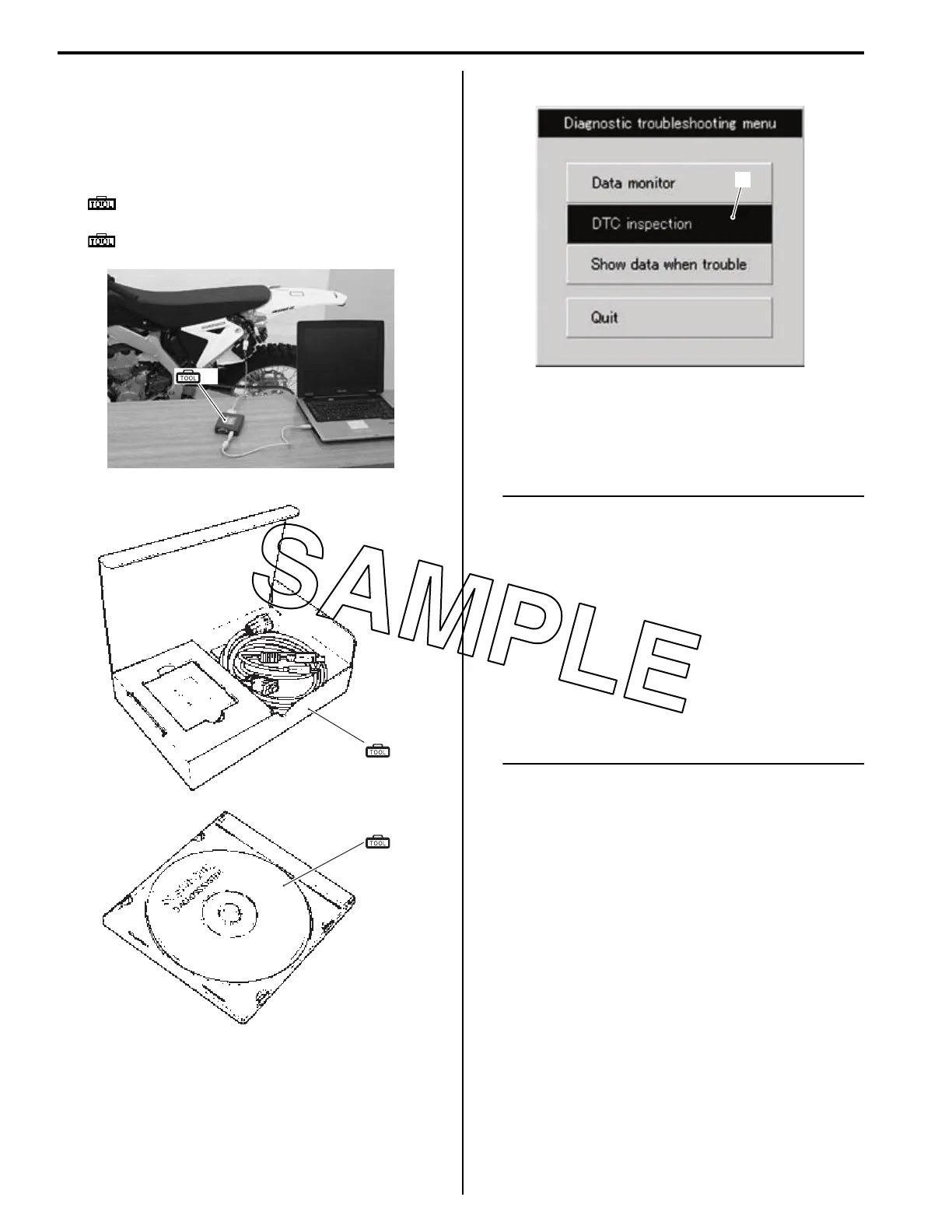
2) Set up the SDS tools. (Refer to the SDS operation
manual for further details.)
Special tool
(A): 09904–41010 (SUZUKI Diagnostic
system set)
(B): 99565–01010–021 (CD-ROM Ver.21)
3) Click the DTC inspection button (1).
4) Start the engine or crank the engine for more than 4
seconds.
5) Check the DTC to determine the malfunction part.
Refer to “DTC Table” (Page 1A-19).
NOTE
• Read the DTC (Diagnostic Trouble Code)
and show data when trouble (displaying
data at the time of DTC) according to
instructions displayed on SDS.
• Not only SDS is used for detecting
Diagnostic Trouble Codes but also for
reproducing and checking on screen the
failure condition as described by
customers using the trigger. (Refer to
“Show Data When Trouble (Displaying
Data at the Time of DTC)” (Page 1A-13).)
• How to use trigger. (Refer to the SDS
operation manual for further details.)
6) After repairing the trouble, clear to delete history
code (Past DTC). Refer to “Use of SDS Diagnosis
Reset Procedures” (Page 1A-12).
7) Close the SDS tool and turn the ignition switch OFF.
8) Disconnect the SDS tool and install the left side
cover.
(A)
IA02J1110009-01
(A)
(B)
I705H1110116-03
1
IA02J1110089-01

 Loading...