LiftCylinderService
g309069
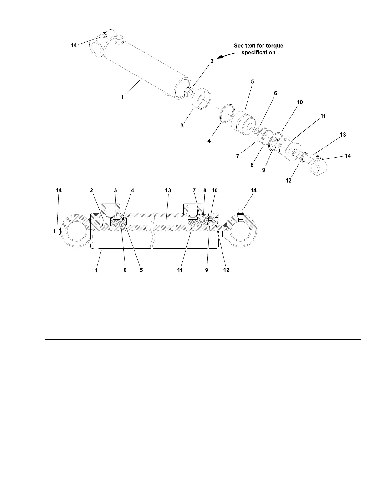
Figure157
1.Tubeassembly
6.O–ring
11.Head
2.Locknut
7.O–ring
12.Wiper
3.Wearring8.Back–upring13.Rodassembly
4.Seal9.Seal14.Greasetting(2used)
5.Piston10.Retainingring
Note:TheliftcylindersusedontheGroundsmasterareallverysimilarregardless
ofthelocationonthemachine.TheliftcylindersusedonGroundsmaster4700-D
#6and#7liftarmshavea19mm(0.750in)diameterrod.Allotherliftcylinders
usedonGroundsmaster4500-Dand4700-Dhavea16mm(0.630in)diameter
rod.Thedisassemblyandassemblyprocedureisthesameforallliftcylinders.
Disassembly(Figure157)
1.Removeoilfromliftcylinderintoadrainpanbyslowlypumpingthecylinder
shaft.Plugbothportsandcleantheoutsideofthecylinder.
Groundsmaster
®
4500-D/4700-D
Page5–173
HydraulicSystem:ServiceandRepairs
19245SLRevA
 Loading...