7-FRONT FORK COMPONENT 52
CHK
ADJ
NO. PART NO.
1 1251300-045000 ZT250-S upper connection decoration nut(chroming) 1 100N.m
2 1251500-050000
-
S upper connection gasket φ18.5×φ39×1
1
3 1250205-023000 GB70.1 inner hexagonal M8X35 (environmental color) 6 25N.m
4 Left shock absorption 1
5 Right shock absorption 1
6 1174100-001000 ZT250-S reflection light 2 after-sales
7 1251100-121093
-
standard bolt M6×25 (environmental color)
2
8
-
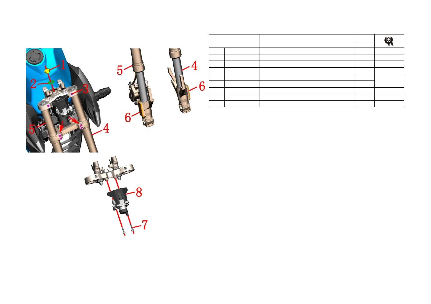
Fig.16 FRONT FORK
COMPONENT
Front shock absorber, upper plate component
Includedereflect
ive sheet
PROCEDURE:
●Uplink board assembly
Locate the faucet lock plug and remove it; remove the nut⑴ and remove the shims⑵. Remove the upper plate
bolt⑶.
●Front left and right shock absorption
Remove the bolts⑶ of the lower plate, and hold the shock absorber in the middle with one hand. Insert a
slottedscrewdriver into the slot of the upper and lower plates to slightly enlarge the slot clearance, and
disassemble the left shockabsorber ⑷ and the right shock absorber⑸. under. Remove the upper plate assembly.
●Reflecting film
Reflective sheets are sold separately for sale (no replacement shock absorption). The heat-reflecting sheet can
be movedback and forth by a hot air blower to reduce the viscosity of the double-sided adhesive after being
heated, and the residualglue should be cleaned after removing the reflector.
●Faucet lock
Using 6# inner hexagon socket remove the faucet lock ⑼.
CAUTION:
●Use a flat-blade screwdriver to enlarge the gap between the upper and lower joint plates without
applyingexcessive force to avoid damage.
●When removing the shock absorption, move it in the direction of axis, do not rotate or swing to prevent
scratches on thesurface.
●
The motorcycle support should be fixed during the disassembly process to prevent accidents caused byincline.
●For the disassembly of the lower link board assembly, see the previous "steering adjustment", which will not
be repeated here.

 Loading...