7-FRONT FORK COMPONENT 54
CHK
ADJ
NO. PART NO.
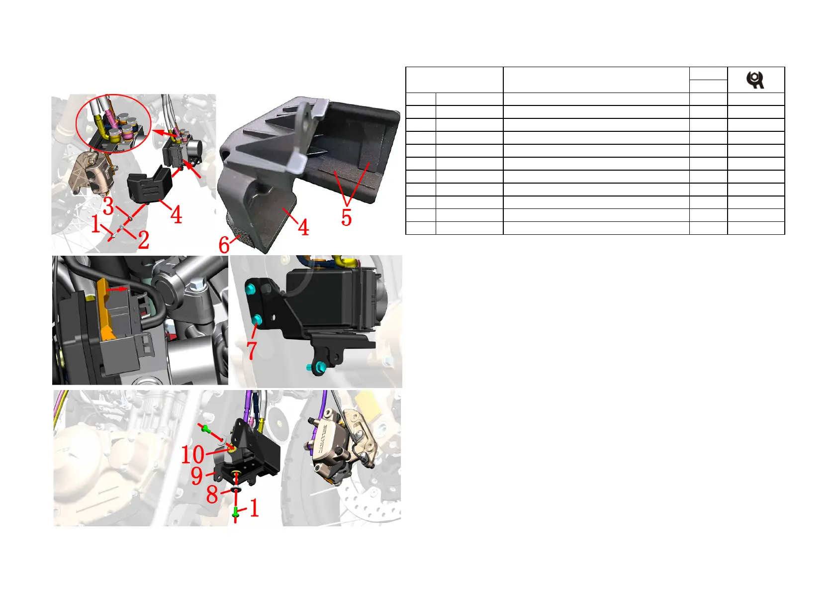
1 1251100-102000 Non-standard bolt M6×16(304 stainless steel) 3
2 1251700-059093
Flanging bushingφ6.4×φ9×8
+
3 1244100-052000 Buffer rubber of flanging bushing (φ8.5×φ14×1) 1
4 1221200-097000 ABS hydraulic control unit protective cover 1
5 1241200-062000 3M sponge pad (50×15×2) 2
6 1244100-081000 Black foam single side tape 0.12
7 1251112-001093 M6×16 Hexagon flange bolts (color zinc) 3
8 1274100-007000 ZT250-S flanging sleeve(φ6.4×φ9×6+φ20×2) 2
9 4021200-027000 KD150-U hydraulic control unit bracket (two-stage) 1
10 1244100-004000 ZT250-S Flanging bushing buffer 2
Fig.18 FRONT FORK
COMPONENT
ABS brake system 1
PROCEDURE:
●Hydraulic control unit components
First use a 14# sleeve to loosen the bolts of the 4 disc brake oil pipes and then tighten them slightly to prevent
oil leakage.
Use 4# inner hexagon to remove bolt ⑴, remove bushing ⑵ and cushion rubber ⑶, then remove protective
cover ⑷. The protective cover ⑷ is pasted with sponge rubber pad ⑸ and tape ⑹.The length of the tape ⑹ is 1
meter. Here you need to cut 2 sections of 60mm in length and paste it to the position shown in the figure
Push the cable connector push rod away and unplug the connector.
Use a 8# sleeve to remove the 3 bolts ⑺ at the bracket, and pull out the hydraulic control unit assembly.
Use a 4# inner hexagon to remove the 2 bolts ⑴ fixing the hydraulic control unit, and remove the bush ⑻ and
bracket ⑼. Remove the cushion rubber ⑽ from the support ⑼.
CAUTION:
●The seat cushion, fuel tank component, side cover and right surrounding component must be removed in
advance.
●
Be sure to disassemble the muffler and engine after they have cooled down completely. The horizontal support
of thevehicle should be fixed before disassembly and assembly work.
●The precautions for brake fluid are described in the previous section.

 Loading...